EN
English – 3
5
1
3
5
2
46
A
MP
1
6
5
24
3
Cable
AMP
plug
pink
green
brown
white
grey
yellow
The tripping point of the preliminary limit switch is automatically
dened when programming the nal lower position. This can be
changed after programming using parameter 6 with K5.
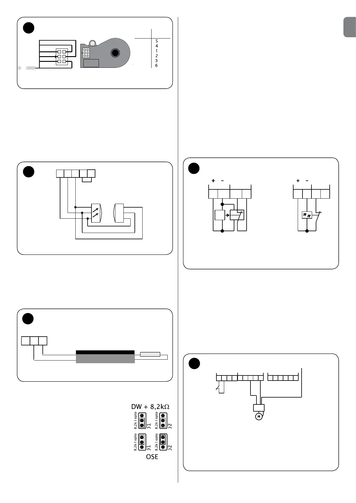
Connecting an OSE optoelectronic contact bar - g. 6
The safety optoelectronic sensitive edge is structured so that a
beam of light is interrupted along its entire length when it is activated.
A receiver is connected to the end of the contact bar so that the
sensitive edge can be controlled along its entire length.
6
OSE optoelectronic
contact bar
Transmitter
Receiver
White
Green
Brown
White
+
SIG
-
Green
Brown
X6
Connecting an 8.2 kΩ sensitive edge - Fig.7
It is possible to directly connect an electric and/or pneumatic
sensitive edge to the UST1-FU device.
The relevant management logic is already integrated in the unit. To
be able to properly control the entire electric circuit of the sensitive
edge, it has to be connected with a resistance (8.2 kΩ).
+
SIG
-
8,2k
•
7
The electrical connection of the sensitive edge is carried out
on terminal J32 (S and +) of terminal block X6.
U-bolts J1 and J2
1-2 inserted = ready for bar DW
as well as SKS with 8.2kOhm
terminal resistance
2-3 inserted = ready for bar OSE
ATTENTION: the two U-bolts must be connected to 8.2
kΩ
and/or to the optical terminals!
Pneumatic sensitive edge connection with operation
test
Make sure U-bolt J4 is inserted. Connect the wires of the sensitive
edge to terminal J32 (S and +) of terminal block X6 and connect the
terminal resistance and sensitive edge in series.
The door must be in contact with the ground so that the sensitive
edge can transmit an impulse to the control unit.
Without the impulse, red LED2 lights up and the next movement is
executed in deadman mode. The error message disappears when
the contact bar is no longer activated.
Partial opening for electronic limit switch
The connection is made through an input on the additional K3 or K3A
module - please refer to the instruction manual enclosed with the module.
C
onnection of a photoelectric barrier - g. 8
It is possible to directly connect a photoelectric barrier to the UST1-
FU device (to terminal block X5) to make the passage safe. If the
infrared beam of the photoelectric barrier is interrupted during the
CLOSING movement of the door, it blocks and reverses the direction
toward the upper nal position.
8
21
3 4
J30
S
Photo
J31
E
S=transmitter
E=receiver
Transmitter and receiver
photoelectric barrier
connection
X5
Safety
photoelectric
barrier
24V DC
current supply
Contact
(opening)
21
3 4
J30
Photo
J31
X5
Reflection photoelectric
barrier connection
ATTENTION:
The switching contact and the positive side of the electronic barrier system
are connected to terminal J30/1 (X5) with positive potential in a one-way
photoelectric barrier with only three connection points.
Remove the jumper from terminal J31 of terminal block X5 if the photoelectric
barrier is connected.
Connection of safety switch for wicket door - g. 9-10
The safety switch is to be connected to terminal J10 terminal of
terminal block X2 in the doors with built-in service wicket door.
Attention! Remove the jumpers (J10)!
9
Cable slackening /
spring breakage
safety or
anti-unwinding
safety switch
Single-phase inverter connection
PE
X2
U
V
W
L1N
N
L1
J11
J12
M1
FU
PE
B2 B1
J10
 Loading...