6
The whole system must be tested by qualified and expert staff who
must perform the tests required, according to the relative risk.
To test WINGO, proceed as follows:
• close the gate;
• disconnect the power supply from the control unit;
• release the gear motor;
• completely open the gate by hand;
• check that the gate does not stick when moving;
• check that when the gate is stopped at any point it remains
motionless;
• check that the safety system and mechanical stops are in good
condition;
• check that the screw connections are perfectly tight;
• check that the lead nut and internally threaded screw are well
greased;
• check that the photocells are clean;
• after the above checks, block the gear motor and power the
control unit.
• WINGO does not have a torque adjustment device; this kind of
adjustment is therefore made by the control unit.
• measure the force of impact as required by EN12453 and
EN12445 standards.
4) Testing
5.1) Disposal
WINGO comprises various types of materials which must be
disposed of in compliance with the laws of the country of installation.
There are no particular dangers or risks deriving from demolition of
the system.
If waste sorting is required, the components should be grouped by
type of material (electrical, aluminium, plastic, etc.).
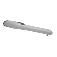
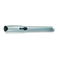
6.1) Models and characteristics
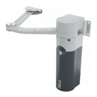
The gate must be moved manually (fig.3) in case of a power failure
or a system fault.
Manual movement allows the gear motor to move freely only if this is
correctly mounted and original accessories have been used.
3) Manual manoeuvre or release
WINGO does not require any special maintenance, but a scheduled
control at least every six months will ensure the gear motor lasts
longer and that the system works correctly and safely.
Maintenance simply involves repeating the test procedure.
5) Maintenance
6) Technical specifications
Power input (Vac/Hz)
Absorbed current (A)
Absorbed power (W)
Incorporated condenser (uF)
Protection level (IP)
Speed (m/s)
Travel (mm)
Max. thrust (N)
Operating temp. (°C Min/Max)
Thermal protection (°C)
Work cycles (%)
Weight (kg)
230/50 110/60
0,5 1
120
510
44
0,016 0,020
320
1500
-20 ÷ +50
140
30
5
WG4000 WG4000/V1

 Loading...