5
GB
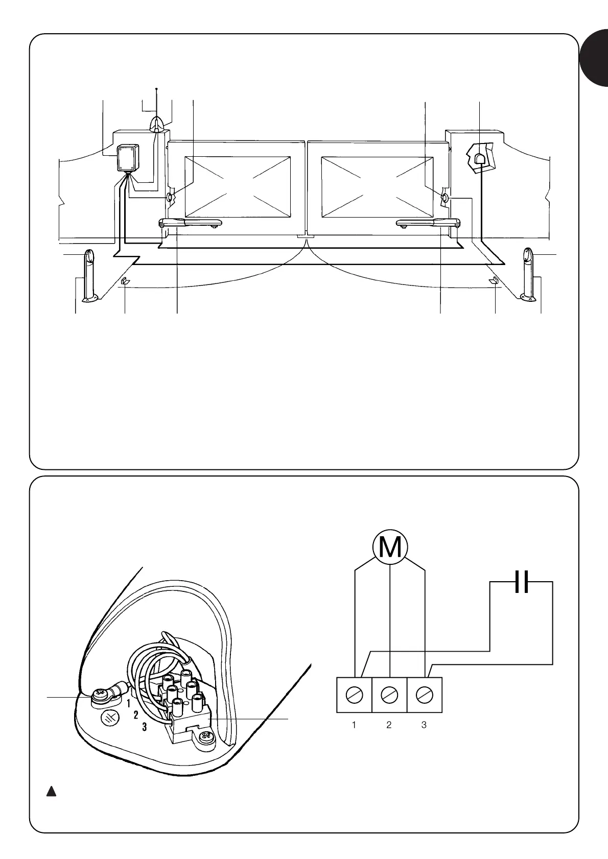
2.4) Typical system layout
7
7
3
1
2
8
7
6
5
4
7
1
2
8
9
1 Column for photocells
2 Pair of opening travel stops
3 Mains power line
4 A400 control unit
5 Aerial
6 Flashing lamp
7 Photocell
8 WINGO actuator
9 Key switch or digital keypad
2.5) Connecting the gear motor
Respecting the numbering in the table, connect the product to the
terminal board (A) following the electrical diagram.
Please remember always to connect the grounding
cable (B) in conformity with the laws in force (EN 60204 -
CEI 64-1, EN 60335)

 Loading...