VBA10201-R.3577.A
- A25 ・ -
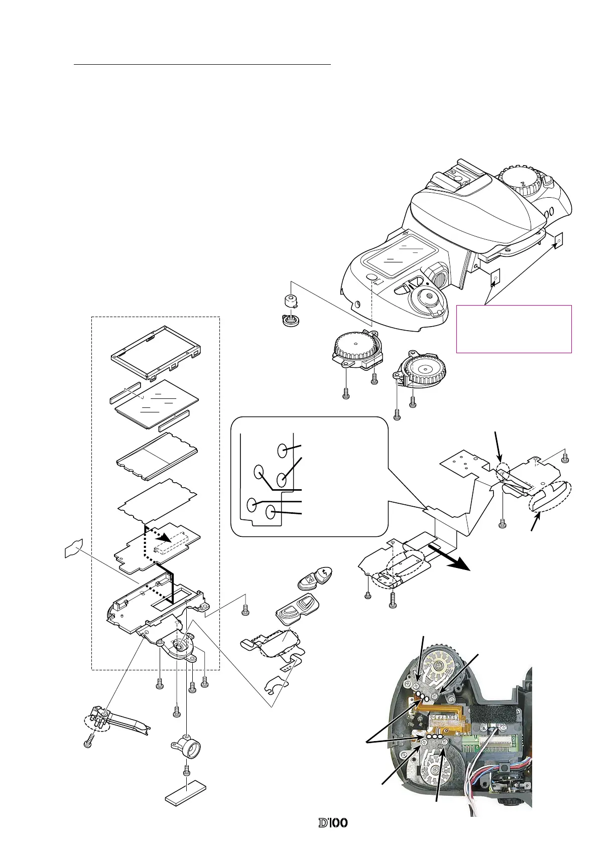
3. Outer LCD Unit, Command Dials and Top Cover FPC
ON
O
FF
s
W
B
M
P
S
A
QUAL
IS
O
F
OR
M
AT
① Afx the C/D FPC #B1018 on the outer LCD Unit and
x it on the top cover using the screw #655 x 4.
② Attach the release switch unit B354, and main and
sub-command dials on the top cover.
③ Remove the connecctor A of the top cover FPC #B2002,
and then insert it in the connector A of the outer LCD unit.
④ Attach the top cover FPC #B2002 to the top cover and
make the soldering bridges.
Soldering Bridge between
the SP Up FPC and Top
cover FPC
Soldering bridge between
the mode dial FPC and
top cover FPC
#807
A
A
Blue:AE-L
White: 〃〃
Soldering bridge between
the C/D FPC and command
dial
Yellow:Metering Mode
Black: 〃 〃
Black: 〃 〃
B
B
C
C
#643
B2002
#654
#725
#340
#339
#342
#773
B1018
#655x5
B325
#613
#328
#666
B354
B1373
B330
#655x2
#655x2
#341
#343
B359
B360
After attaching tapes#488x2 to
top cover, make holes by some
sharp point tool in order to
prevent from rolling in.
#488x2
①
①
②
②
● Tighten the screws in order
of
①
to
② .
 Loading...