VBA10201-R.3577.A
- A29 ・ -
ADJUSTMENT FOR THE BODYBACK
● Measure from the bayonet surface to the external rail.
The 4 ×-marked positions are where to be measured.
Standard : 48.2±0.015 mm / Tolerance for atness :
within 0.015 mm
● If the measured value is out of the standard, unfasten
the screws xing the front body and the rear body to
move the front body back and forth.
Or, adjust it, placing a washer between the docking
surface of front and rear bodies.
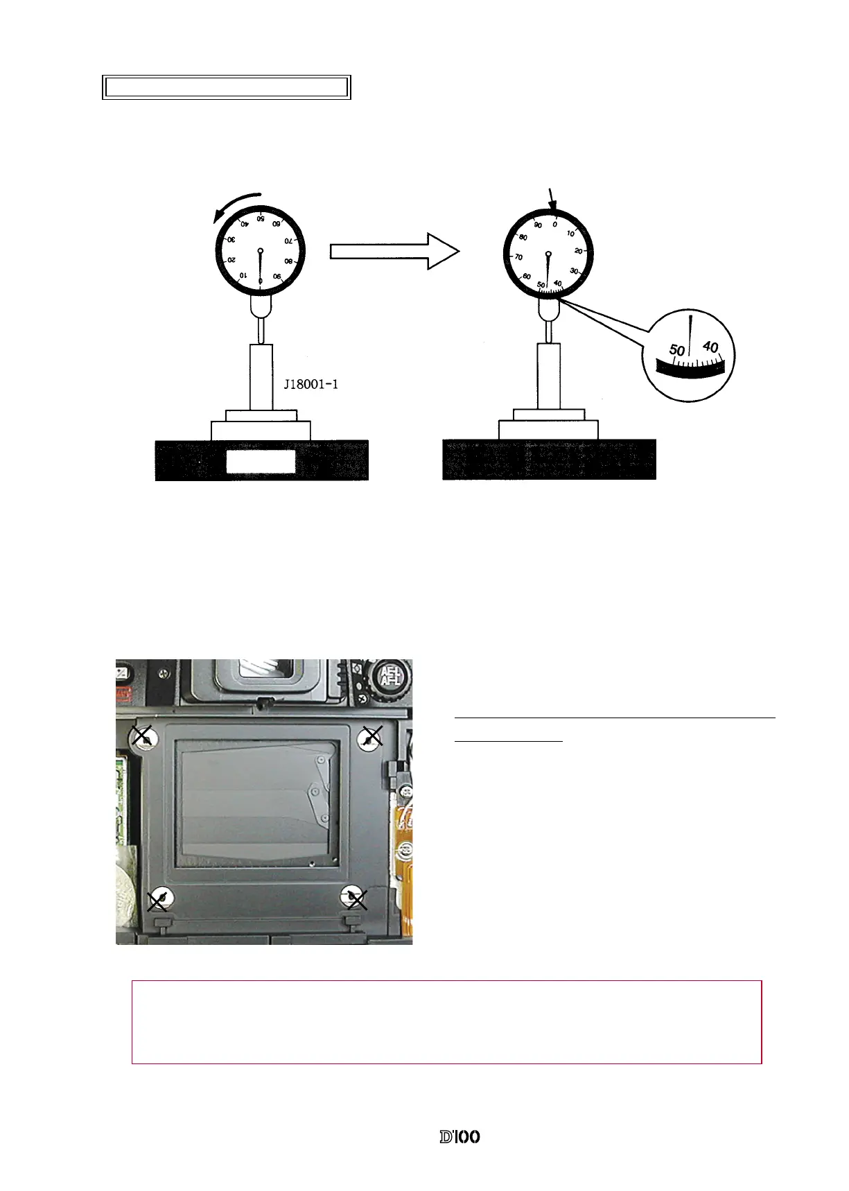
● Set the "0" position of the dial gauge.
①
Put the tool (J18001-1) on the surface plate and set the dial gauge to "0".
②
From the "0" position set in process
①
, turn the dial gauge by “0.47mm” in an arrow direction. (This is
the "0" position of D100.)
③
Measure the body back wiht the "0" position of D100 as a reference.
"0" position of D100
Surface
plate
Note: Some bodies have a washer on the CCD PCB attaching position. (Red marking is on the
surface.) When disassembling or relacing the CCD PCB, put the washer where it was in.
 Loading...