E-33
Assembly
5
Be sure to read the “Safety Precautions” and “Notes on Handling the Product” at the beginning of
this manual and follow all instructions given there before assembling the microscope. In order to
prevent electrical shock, also be sure to press the power switch to the “○” position to turn the
power off before assembly.
1
Assembling the Basic Set
The following steps 1 to 3 are required for the TS100/TS100-F.
For the TS100LED MV/TS100LED-F MV, start from the step 4.
1
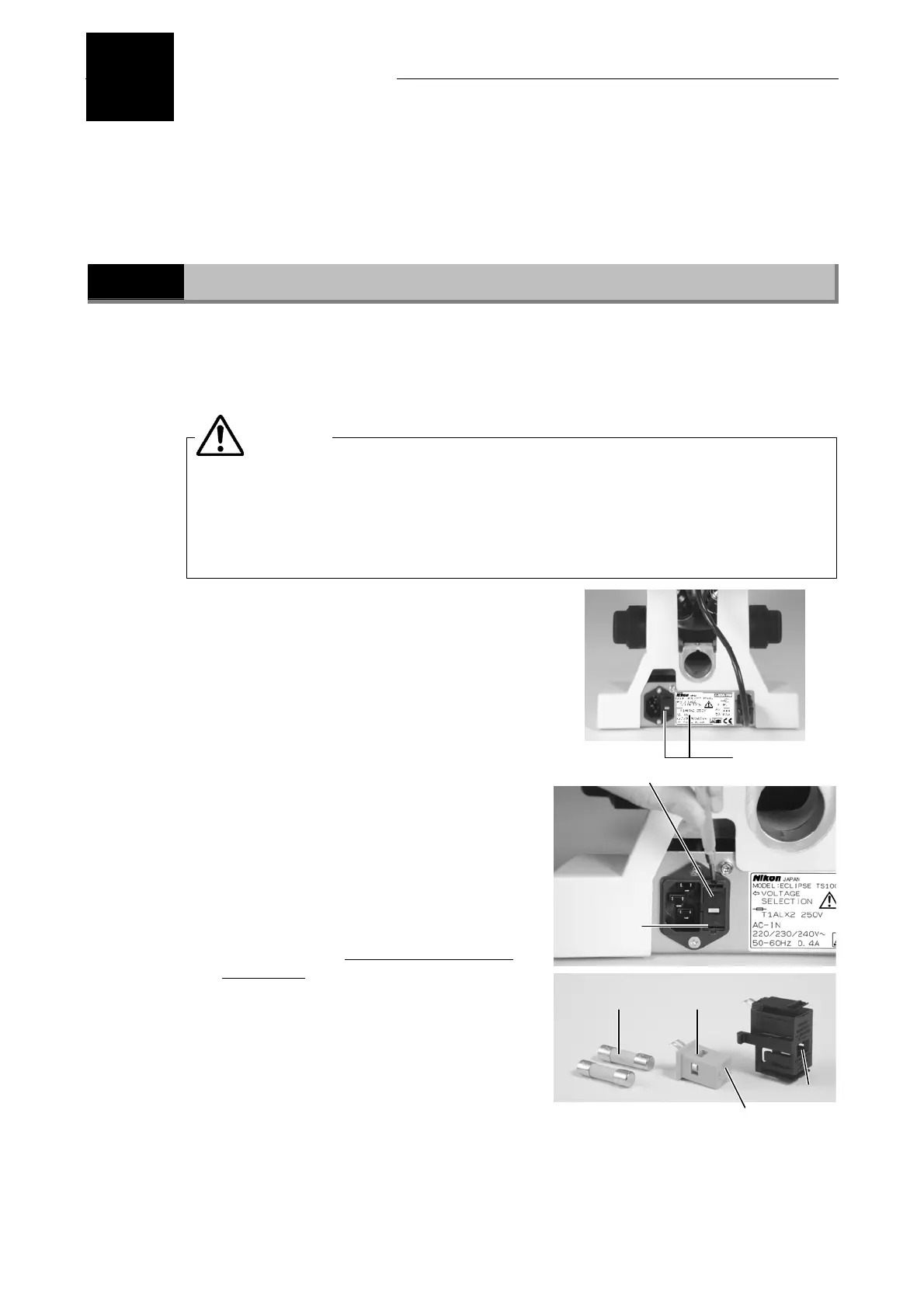
Confirming the input voltage (for TS100/TS100-F only)
Make sure that the input voltage indicated on both the nameplate on the rear
panel of the microscope and to the immediate right of the AC inlet are the same as
your local voltage. Do not use the microscope if the local voltage differs from that
required by the microscope. Follow the instructions below if this is the case. Use
of the microscope under the incorrect voltage may cause over-heating due to
over-current, possibly resulting in a fire and damaging the microscope.
• If the voltage indicated on the nameplate differs
from local voltage, do not turn on the power but
contact your nearest Nikon representative
immediately.
• If the voltage indicated to the immediate right of
the AC inlet differs from local voltage, change the
input voltage setting as described below before
turning on the power. The following values may
be set for the input voltage.
• If the nameplate reads “100/110/120 V ∼”, the
input voltage may be set to 100, 110 or 120 V AC.
• If the nameplate reads “220/230/240 V ∼”, the
input voltage may be set to 220, 230 or 240 V AC.
Switching the voltage
Tools needed: Flathead screwdriver
(1) Press the power switch to the “○” position to
turn off the power. Unplug the power cord if it
is connected.
(2) Remove the fuse holder using a precision
flathead screwdriver. (Use the tip of the
minus driver to push the two lock plates
toward the center of the fuse holder. The fuse
holder pops out from the AC inlet.)
(3) Remove the fuses and pull out the voltage
selector inside the fuse holder.
(4) Set the voltage selector so that the voltage displayed in the window of the fuse holder is
the same as the local voltage to be used.
(5) Re-attach the fuses and fuse holder in their original locations.
Input voltage
indications
Lock plate
Fuse holder
WARNING
Fuses Voltage selector
Voltage display
Window
 Loading...