4
14
4.2
4.3
32
29
15
14
21
102
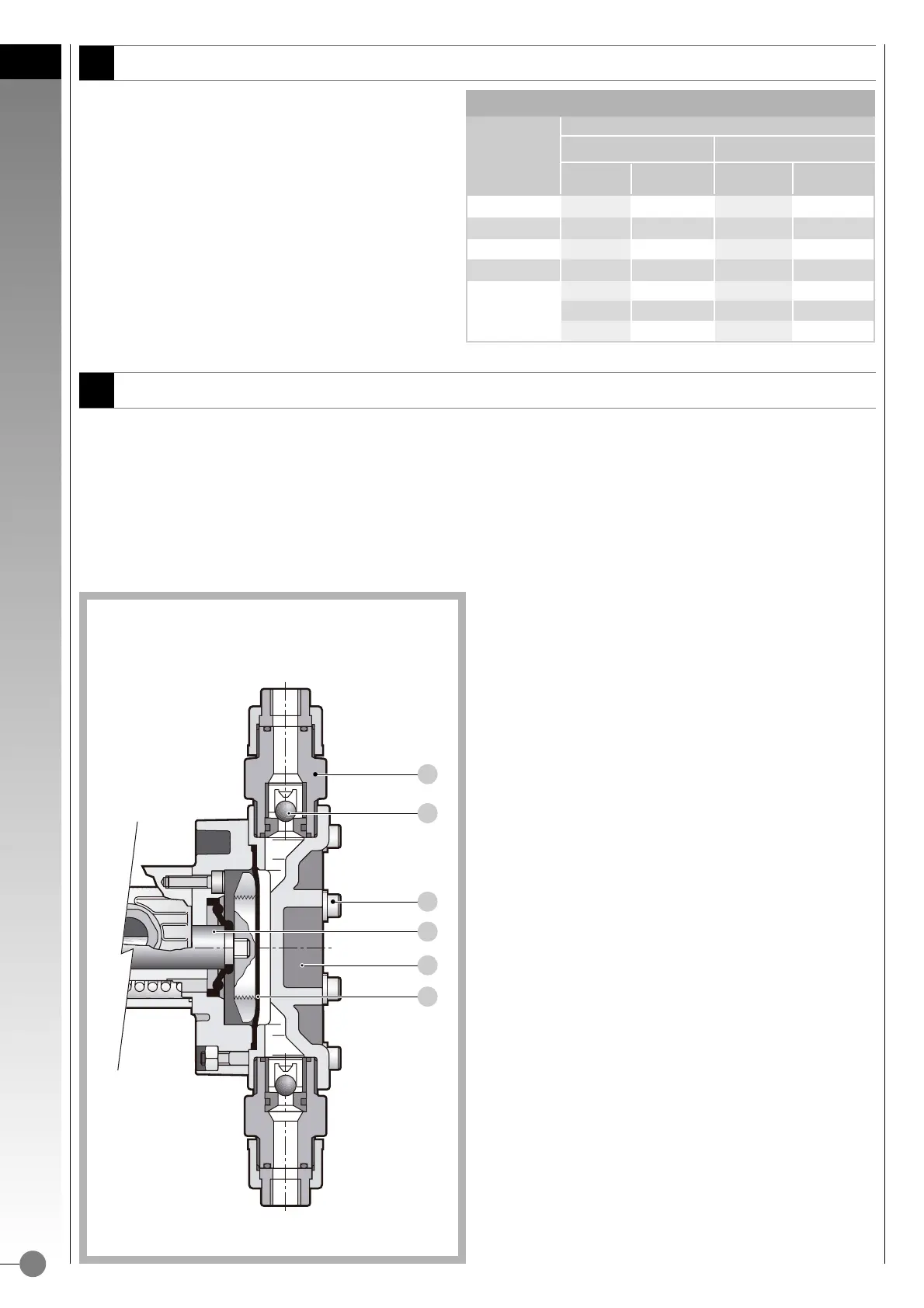
Fig. 18
A)
• Unscrew valve housing (pos.14).
• Take note of the arrangement of the various components of the
valve unit.
• Extract the valves.
• Clean carefully their seat.
• If necessary, replace seats and valves.
• Reassemble valve unit exactly as before noted.
• Screw back valve housing (pos.14)
B)
• Diaphragm (pos. 32)
• Take off pump head screws (pos. 29).
• Remove pump head (pos.21).
• Unscrew the diaphragm (pos.32) by turning it counterclockwise.
• Before screwing up the diaphragm, grease its thread (pos.102)
(threaded top end of the slide).
• Screw up the diaphragm and make sure that it reaches its end
position.
• Re-assemble the pump head (pos. 21), checking valves groupes
arrangement.
• Gradually screw back in pos. 29 (screws).
Do not overtighten: - for MB type max 3,5 Nm
Do not overtighten: - for MC type max 5 Nm.
• Valves (pos. 15).
To dismantle the valves it is necessary to unscrew, first the valve housing (pos.14) and take off the valve balls.
Assuming that cleaning of the valves is required, proceed as follows on the valve units one at a time:
DIAPHRAGM 32 1 32 1
VALVE SEATS 5 2 5 2
VALVE GUIDES
6262
VALVE
15 2 15 2
8282
VALVE SEAL
9292
76
EXECUTION (HEAD BODY MATERIAL)
DENOMINATION
PP A AISI 316L
POSITION
PIECES NO.
POSITION
PIECES NO.
Table G
DISMANTING ( AND REASSEMBLY )
MAINTENANCE
• We suggest the purchasing of a series of essential details
for the preventive maintenance of diaphragm pump head
(table G).
For the positions see pump head sectional drawing.
PREVENTIVE MAINTENANCE
 Loading...