3.1.3
Initialization
The printer is initialized when the power is turned on or when the parallel interface signal, I-PRIME,
is received from the host computer.
Initialization is started when the RST OUT 1 signal is sent from the reset circuit
(47
pin
1)
to
911,
and
RST OUT-P is sent from
Ql
1
to
98
and Q6. BUSY signal is active during initialization stage.
When reset is completed, ROM program execution starts with mode setting of Qll,
98
and Q6.
Next a memory (ROM and RAM) check is performed, RAM is initialized, and the carriage is homed.
The program finally establishes the interface signals (output level of ACK signal, BUSY signal, etc.),
lights the SELECT indicator, and informs the host computer that the printer is ready for data
reception (in the data reception wait state), thus completing the initialization.
3.1.4
Interface control
(1)
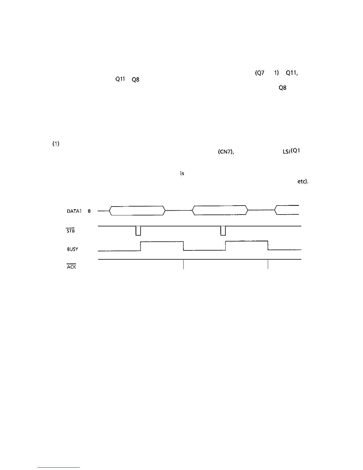
Parallel interface
The data from the interface is input through connector
(CN7).
and the interface
LSI
(Ql
1:
MSM6990) latchesthis input data in sync with the ST8 signal.
The BUSY signal is on during processing of this data. When the processing is completed, the
BUSY signal is turned off, and an ACK signal
i.s
sent to request more data.
The BUSY signal is also on when data cannot be received (when the receiving buffer is full,
etc).
DATA1
to
8
---(----~)-----(-----
Tii
u
tl
BUSY
I
ZK
3-5