3.1.5 Printhead drive circuit
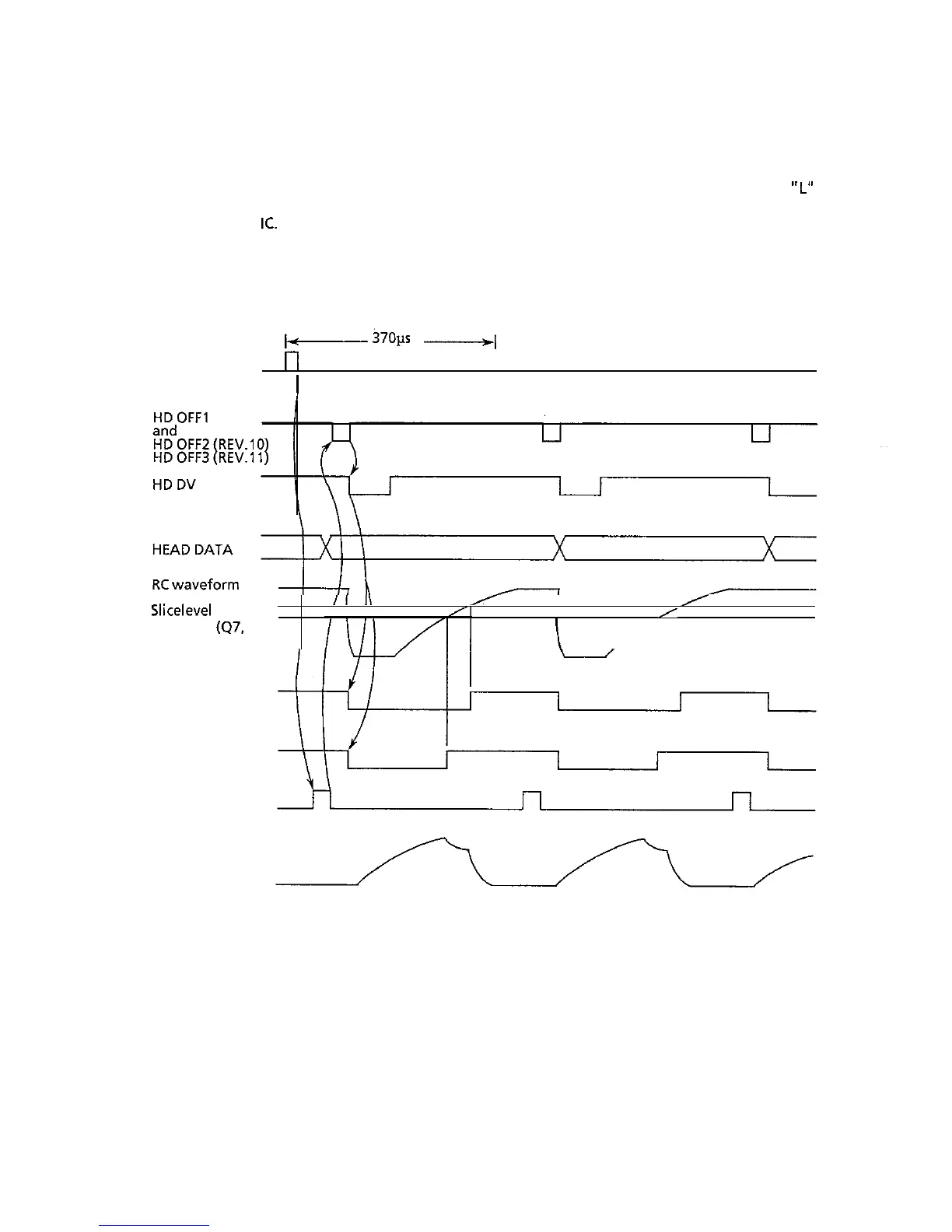
This circuits is used to drive the head magnets corresponding to HEAD DATA 1 to 24 (the head pins)
by the HD DV signal (even or odd trigger) for printing purposes. When-the HD DV signal is at
“L”
level, the head driving time is determined by the HD DV pulse width. This pulse is developed by a RC
circuit within the
IC.
The pulse width of HD DV varies with the number of pins being driven. The
drive time is lengthened if a larger number of pins are to be driven, but shortened if less pins are to
be driven.
IPT
b-
37011s
------+I
r-l
rl
rl
I
Slicelevel
(47.9 pin)
/I
I\
I
I
I
II I\
/
Slicelevel
(47,
11 pin)
I
EN (ENABLE)
COM
(COMMON)
Serial data
transfer
ODD and EVEN
call current
waveform
3-6
 Loading...