3.1.7
Line feed circuit
The line feed motor shaft is held stationary by the
LF
HOLD signal (holding current:
approx.
25
mA)
while it is at a stopped position.
During line feed operation, the line feed motor is driven by a large current supplied in accordance
with
LF
OVD signal.
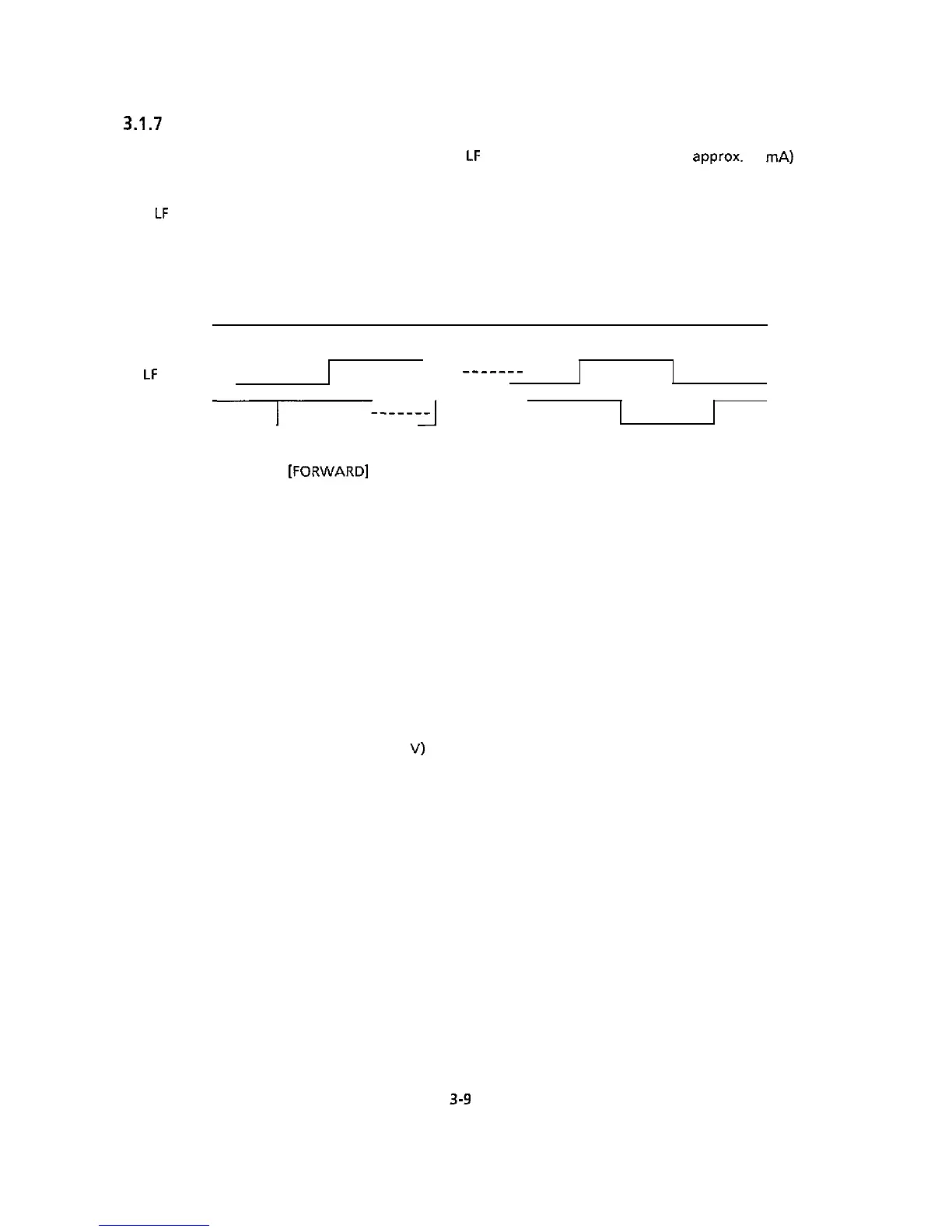
LFOVD
LF
PHA
-____--
LFPHB
-1
r------I]
[FORWARD]
[REVERSE]
3.1.8 Alarm circuits
(1)
Fault alarm circuit (in Power Supply Unit)
This is a protective circuit which causes the AC fuse to open when a fault occurs in the
printhead drive circuit, space motor drive circuit, or their peripheral circuits, thus preventing
component failure.
For this purpose, this circuit monitors the drive time using the HDALM and SPALM signals
interlocked with the overdrive signal of each drive circuit. If the drive time of any drive circuit
exceeds the specified time, the drive circuit fault alarm circuit sends an ALM signal (high) to
turn on the SCR.
This causes the secondary coil (40
V)
of the transformer to be short-circuited, causing an
overcurrent to flow through the primary coil and making the AC fuse open.
3-9
 Loading...