4 - 7
4 Inverter Control
EtherCAT Communication Unit USER’S MANUAL (3G3AX-MX2-ECT)
4-2 Control with the Position Control Unit
4
4-2-4 Sample Program
This section explains a configuration that uses CJ1W-NCx82 as the master, and one MX2 inverter on
which an EtherCAT Communication Unit (node address: 17) is mounted as the slave.
The shared parameter settings of CJ1W-NCx82 are as follows.
The control information and status information of the EtherCAT Communication Unit is allocated to the
addresses below.
• Control information (master to slave)
• Status information (slave to master)
4-2-4 Sample Program
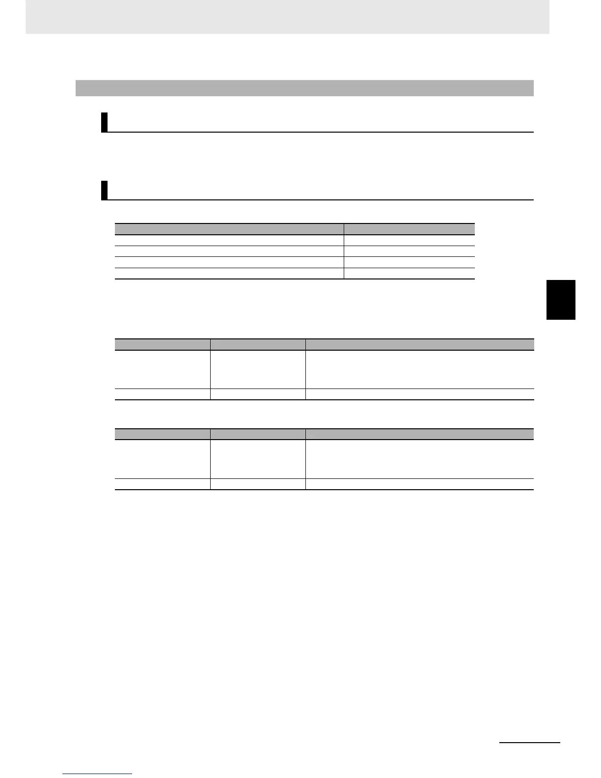
Configuration
Parameter settings
Parameter name Set value
Remote I/O Output Memory Area Selection CIO area
First word of remote I/O Output memory area 3800
Remote I/O Input Memory Area Selection CIO area
First word of remote I/O Input memory area 3900
Word Address Meaning
n CIO 3800 Command
Bit 0: Forward/stop
Bit 1: Reverse/stop
Bit 7: Fault reset
n + 1 CIO 3801 Frequency reference (increments of 0.01 Hz)
Word Address Meaning
m CIO 3900 Command
Bit 0: During forward operation
Bit 1: During reverse operation
Bit 3: Fault
m + 1 CIO 3901 Output frequency monitor (increments of 0.01 Hz)

 Loading...