5 - 3
5 CiA402 Drive Profile
EtherCAT Communication Unit USER’S MANUAL (3G3AX-MX2-ECT)
5-1 Inverter State Control
5
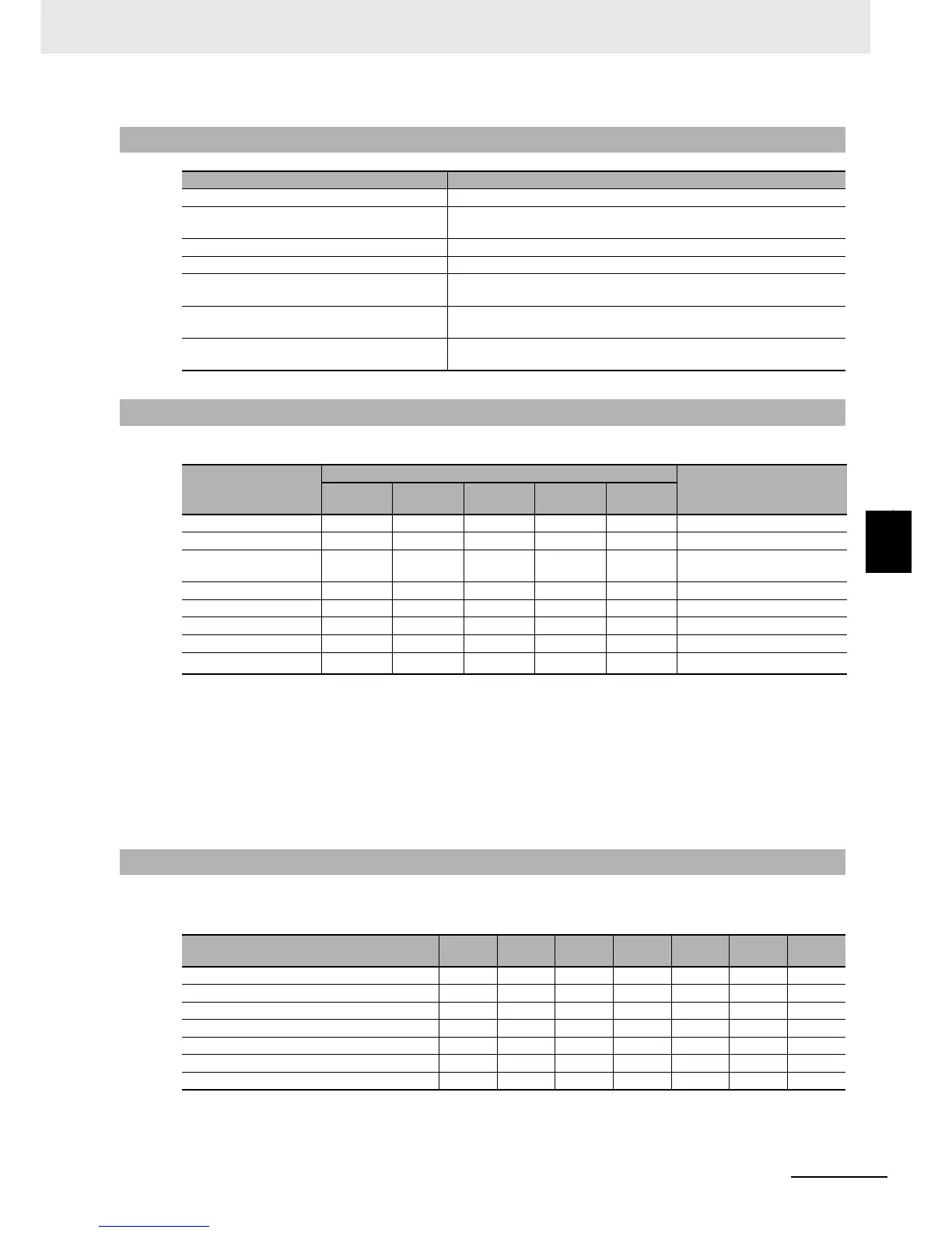
5-1-2 State Descriptions
The state is controlled by combining the bits in Controlword (6040 hex), as shown in the following table.
(Notes) fr = Fault reset, eo = Enable operation, qs = Quick stop, ev = Enable voltage, so = Switch on
*1 The state automatically transitions to the Enable operation state after the Switch on state.
*2 Operation when bit 7: Fault reset turns ON.
Fault state : Fault are cleared and the state transitions to Switch on disabled.
: If there are any warnings (6401 hex: Statusword bit 7), they are reset.
State other than Fault : If there are any warnings (6041 hex: Statusword bit 7), they are reset.
: The state will change according to command bits 0 to 3.
*3 When Fault reset is executed with bit 7, set the bit back to 0 before giving the next command.
The state is indicated by the combination of bits in Statusword (6041 hex), as shown in the following
table.
(Notes) sod = Switch on disabled, qs = Quick stop, ve = Voltage enabled, f = Fault, oe = Operation enabled,
so = Switched on, rtso = Ready to switch on
5-1-2 State Descriptions
State Details
Not ready to switch on The power supply is turned ON and initialization is being executed.
Switch on disabled Initialization has been completed.
Parameters can be set.
Ready to switch on Parameters can be set.
Switched on Parameters can be set.
Operation enabled Inverter can be controlled.
Parameters can be set.
Fault reaction active There was an error in the inverter and the cause is being determined.
Parameters can be set.
Fault There is an error in the inverter.
Parameters can be set.
5-1-3 Command Coding
Command
Controlword bit
Transition
Bit 7
fr
Bit 3
eo
Bit 2
qs
Bit 1
ev
Bit 0
so
Shutdown - - 1 1 0 2, 6, 8
Switch on - 0 1 1 1 3
Switch on +
enable operation
-1111
3 + 4
*1
Disable voltage - - - 0 - 7, 9, 10
Quick stop - - 0 1 - 7, 9, 10
Disable operation - 0 1 1 1 5
Enable operation - 1 1 1 1 4
Fault reset
0
1
*2*3
----15
5-1-4 State Coding
State
Bit 6
sod
Bit 5
qs
Bit 4
ve
Bit 3
f
Bit 2
oe
Bit 1
so
Bit 0
rtso
Not ready to switch on 0 0 - 0 0 0 0
Switch on disabled 1 1 - 0 0 0 0
Ready to switch on 0 1 - 0 0 0 1
Switched on 0 1 1 0 0 1 1
Operation enabled 0 1 1 0 1 1 1
Fault reaction active 0 1 - 1 1 1 1
Fault 01- 1000

 Loading...