71
CIO Area Allocations Section 4-2
User Settings
Note The reserved words are regularly refreshed with all zeroes.
The functions of the allocated CIO Area words are described in the following
section.
4-2-2 Details of the Allocated CIO Area Words
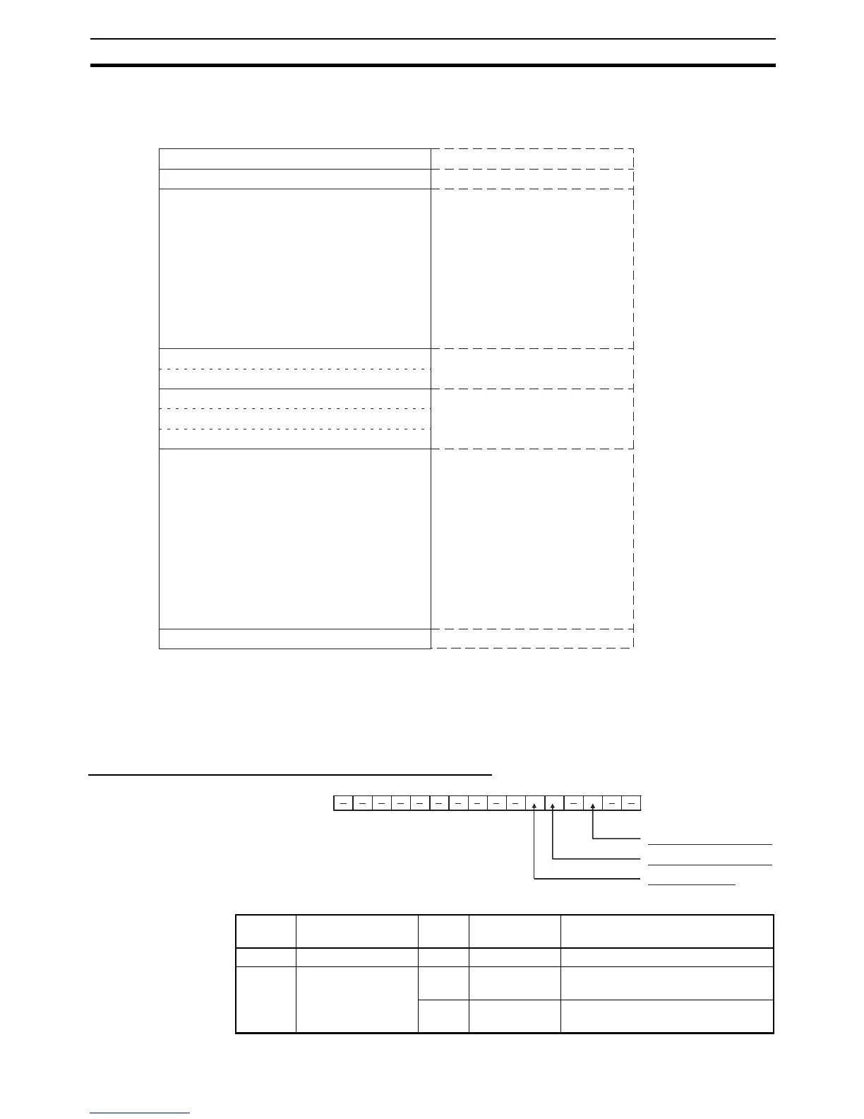
Unit Control Bits (CPU Unit to EtherNet/IP Unit) (n)
Unit control bits
(Reserved)
Unit status 1
Unit status 2
Communications status 1
Communications status 2
Communications status 3
(Reserved)
FINS/TCP Connection Status
CPU Unit → EtherNet/IP Unit
EtherNet/IP Unit → CPU Unit
EtherNet/IP Unit → CPU Unit
EtherNet/IP Unit → CPU Unit
EtherNet/IP Unit → CPU Unit
EtherNet/IP Unit → CPU Unit
Offset
Bit
Data direction
n
n+1
n+2
n+3
n+4
n+5
n+6
n+7
n+8
n+9
n+10
n+11
n+12
n+13
n+14
n+15
n+16
n+17
n+18
n+19
n+20
n+21
n+22
n+23
n+24
15 8 7 0
0
1
2
3
4
5
6
7
8
9
10
11
12
13
14
15
16
17
18
19
20
21
22
23
24
Tag Data Link Start Bit
Tag Data Link Stop Bit
15 14 13 12 11 10 9 8 7 6 5 4 3 2 1 0
n
Adjust Clock Bit
Bit Switch Status Manipulated
by
Unit operation
0 to 1 (Not used.) --- --- ---
2 Tag Data Link Start
Bit
ON User The tag data link starts when this bit
is switched from OFF to ON.
OFF Unit Turned OFF by Unit after the tag
data link starts operating.

 Loading...


