3 - 3
3 Part Names and Basic Procedures
E5@C Digital Temperature Controllers User’s Manual (H174)
3-2 Power ON
3
3-2 Power ON
Operation will start as soon as you turn ON the power supply to the E5@C.
The following default settings will be used when operation starts.
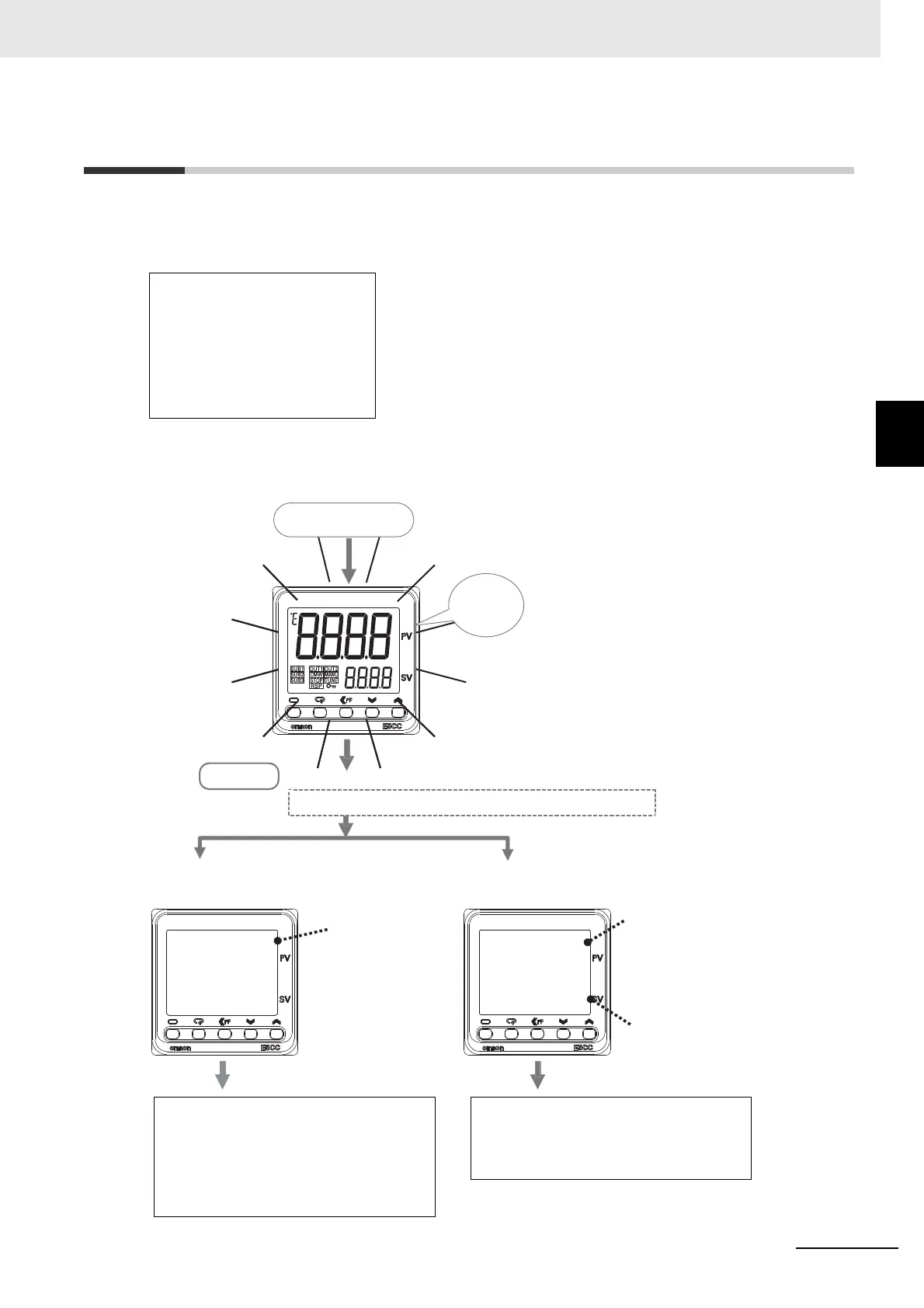
Standard Models
After the power comes ON, all indicators and displays will light for approximately 1 second, and then the
operation display will appear.
The top display will show the PV and the bottom display will show the SP.
• Input type 5:
K thermocouple
• ON/OFF control
*1
• Alarm: Upper-limit alarm
*2
• Set point: 0°C
*1 The default setting for Position-proportional Models is floating control
operation.
*2 If the Controller is equipped with HB/HS alarm detection, the default
setting for the Auxiliary Output 1 Assignment is for heater alarms.
Therefore, the alarm 1 function is disabled and the Alarm 1 Type is not
displayed. To enable alarm 1, set an output assignment to alarm 1.
s.err
0
25
0
C
• Resistance Thermometer Connected
or
• Temperature Sensor Not Connected
• Thermocouple Connected
SP
*The default setting is 0°C.
s.err:
An input error
is displayed.
The default setting of the input type is for a K thermocouple.
The operation display appears.
Operation Level
Power ON
Everything
lights for
approx. 1 s.
The PV that is measured by the
temperature sensor is displayed.
K Thermocouple Connected:
The correct temperature is
displayed.
Other Thermocouple Connected:
The correct temperature is
not displayed.
If you are not using a K thermocouple, set
the Input Type parameter to the correct
sensor type in the Initial Setting Level.
Refer to step 2 on 3-13.
• Change the setting of the Input Type
parameter to a resistance thermometer in
the Initial Setting Level.
Or
• Connect a temperature sensor.
Refer to step 2 on 3-13.

 Loading...