4 Basic Operation
4 - 38
E5@C Digital Temperature Controllers User’s Manual (H174)
4-11 Alarm Hysteresis
• The hysteresis of alarm outputs when alarms are switched ON/OFF can be set as follows:
• Alarm hysteresis is set independently for each alarm in the Alarm 1 to 4 Hysteresis parameters (Initial
Setting Level).
• For all alarms except for MV alarms, the default is 0.2 (°C/°F) for temperature inputs and 0.02% FS
for analog inputs. The default is 0.50(%) for MV alarms.
• The standby sequence can be used so that an alarm will not be output until the process value leaves
the alarm range once and then enters it again.
• For example, with a lower-limit alarm, the process value will normally be below the set point, i.e.,
within the alarm range, when the power supply is turned ON, causing an alarm to be output.
If the lower-limit alarm with a standby sequence is selected, an alarm will not be output until the pro-
cess value increases above the alarm set value, i.e., until it leaves the alarm range, and then falls
back below the alarm set value.
Restart
• The standby sequence is canceled when an alarm is output. It is, however, restarted later by the
Standby Sequence Reset parameter (Advanced Function Setting Level). For details, refer to the
Standby Sequence Reset parameter in Section 6 Parameters.
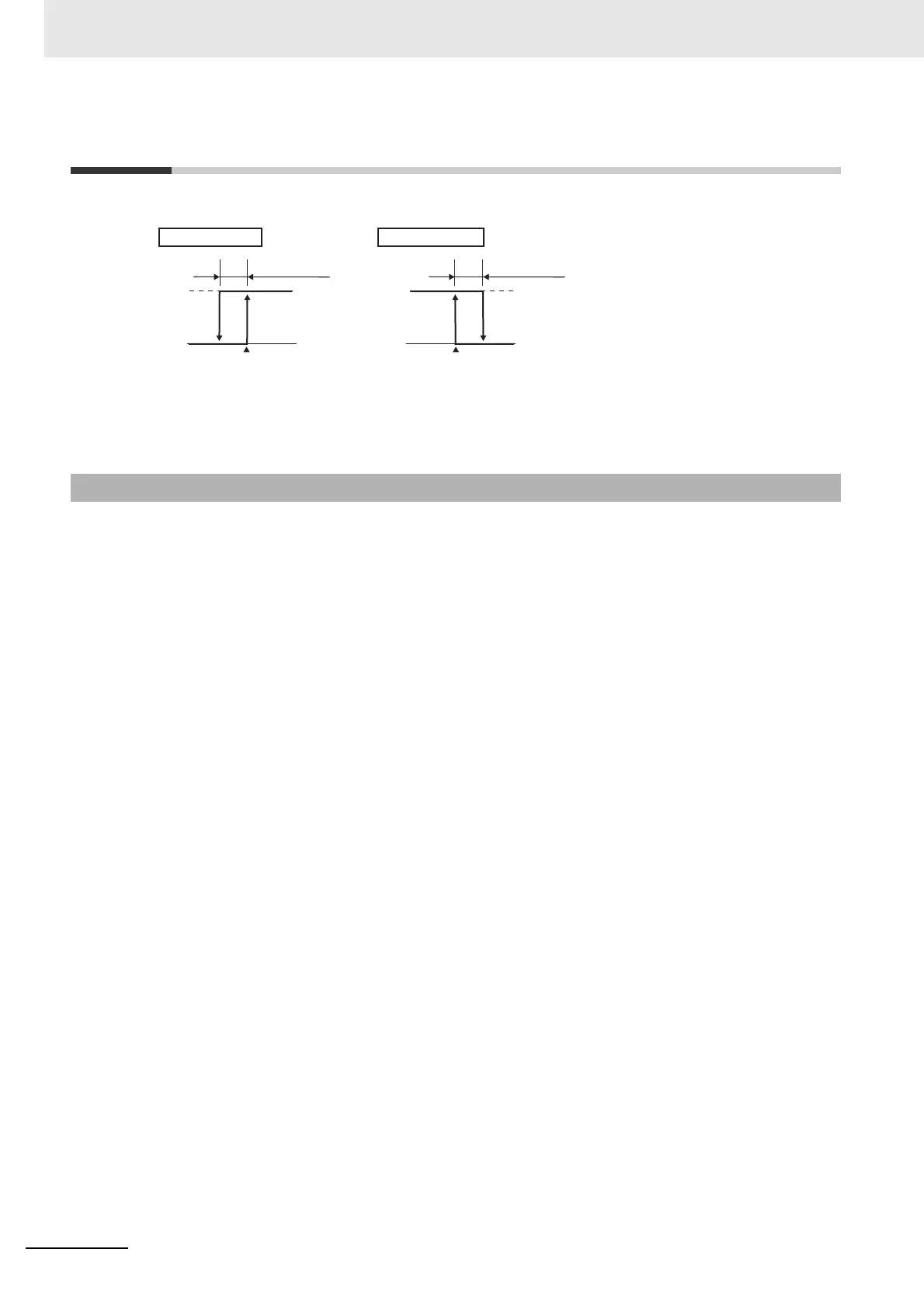
4-11-1 Standby Sequence
ON
OFF
ON
OFF
Upper-limit alarm
Alarm hysteresis
Alarm value
Lower-limit alarm
Alarm hysteresis
Alarm value

 Loading...