2 - 29
2 Preparations
E5@C Digital Temperature Controllers User’s Manual (H174)
2-2 Using the Terminals
2
2-2-2 E5CC-U Terminal Block Wiring Example
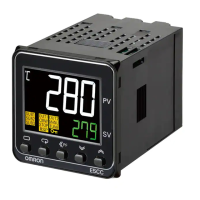
Terminal Arrangement
The terminals block of the E5CC-U is divided into four types of terminals: control output 1, sensor input,
auxiliary output, and input power supply.
Precautions for Correct Use
When you purchase the Digital Controller, it will be set for a K thermocouple (input type = 5) by
default. If a different sensor is used, an input error (s.err) will occur. Check the setting of the
Input Type parameter.
Model Numbers
The specification for control output 1 is given in the following location in the model number.
Terminal Details
Do not connect anything to the terminals that are shaded gray.
2-2-2 E5CC-U Terminal Block Wiring Example
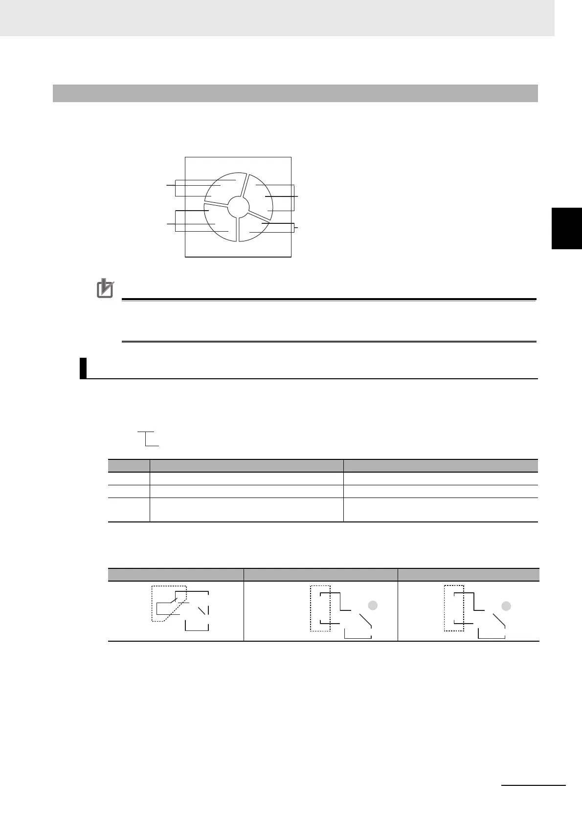
Control Output 1
Code Output type Specification
RW 1 relay output, SPDT contacts 250 VAC, 3 A (resistive load)
QX 1 voltage output (for driving SSR) 12 VDC, 21 mA
CX 1 linear current output 4 to 20 mA DC or 0 to 20 mA DC with load of
500 Ω max.
RW QX CX
D
F
E
G
H
I
J
K
B
A
C
Control output 1
Sensor input
Auxiliary output
Input power supply
E5CC-@@ @ @ U M-@@@
Control output 1
Relay output
Control output 1
D
F
E
−
+
F
E
D
Voltage output (for
driving SSR)
Control output 1
Control output 1
−
+
F
E
D
Linear current
output

 Loading...