5 Advanced Operations
5 - 40
E5@C Digital Temperature Controllers User’s Manual (H174)
Simple Transfer Scaling
• Reverse scaling is possible by setting the Simple Transfer Output 1 Lower Limit parameter larger
than the Simple Transfer Output 1 Upper Limit parameter. If the Simple Transfer Output 1 Lower
Limit and Simple Transfer Output 1 Upper Limit parameters are set to the same value, the simple
transfer output will be output continuously at 0%.
• If the Simple Transfer SP, Simple Transfer SP during SP Ramp, or Simple Transfer PV is selected,
the Simple Transfer Output 1 Upper Limit and Simple Transfer Output 1 Lower Limit parameters
will be forcibly initialized to the respective upper and lower setting limits if any of the following
parameters is changed: Input Type, Scaling Upper Limit, Scaling Lower Limit, Set Point Upper
Limit, Set Point Lower Limit, or Temperature Unit. If the Simple Transfer MV (Heating) or Simple
Transfer MV (Cooling) is selected, the Simple Transfer Output 1 Lower Limit and Simple Transfer
Output 1 Upper Limit parameters will be initialized to 100.0 and 0.0, respectively, when a switch is
made between standard control and heating/cooling control using the Standard or
Heating/Cooling parameter.
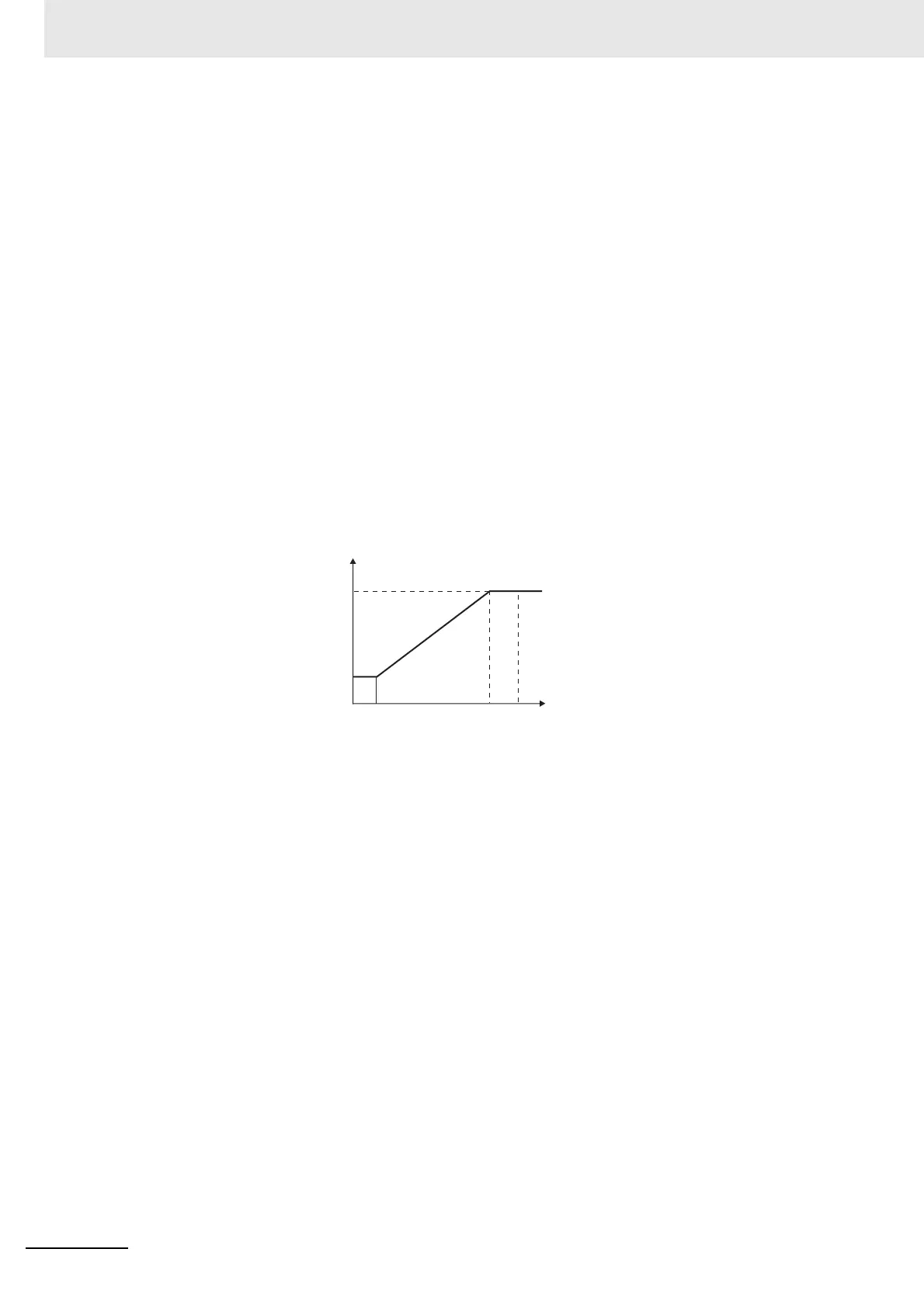
• The output current when the Simple Transfer Output 1 Signal parameter is set to 4 to 20 mA, the
Simple Transfer Output 1 Upper Limit parameter is set to 90.0, and the Simple Transfer Output 1
Lower Limit parameter is set to 10.0 is shown in the following graph.
• For scaling from 0.0% to 100.0%, the output for −5.0 to 0.0 will be the same value as for 0.0%, and
the output for 100.0 to 105.0 will be the same value as for 100.0%
Simple Transfer
Output 1 Lower Limit
(The above graph is for when the simple transfer
output 1 signal is set to 4 to 20 mA.)
Simple Transfer
Output 1 Upper Limit
20
1009010
4
0
Output current (mA)
MV (%)

 Loading...