A Appendices
A - 40
E5@C Digital Temperature Controllers User’s Manual (H174)
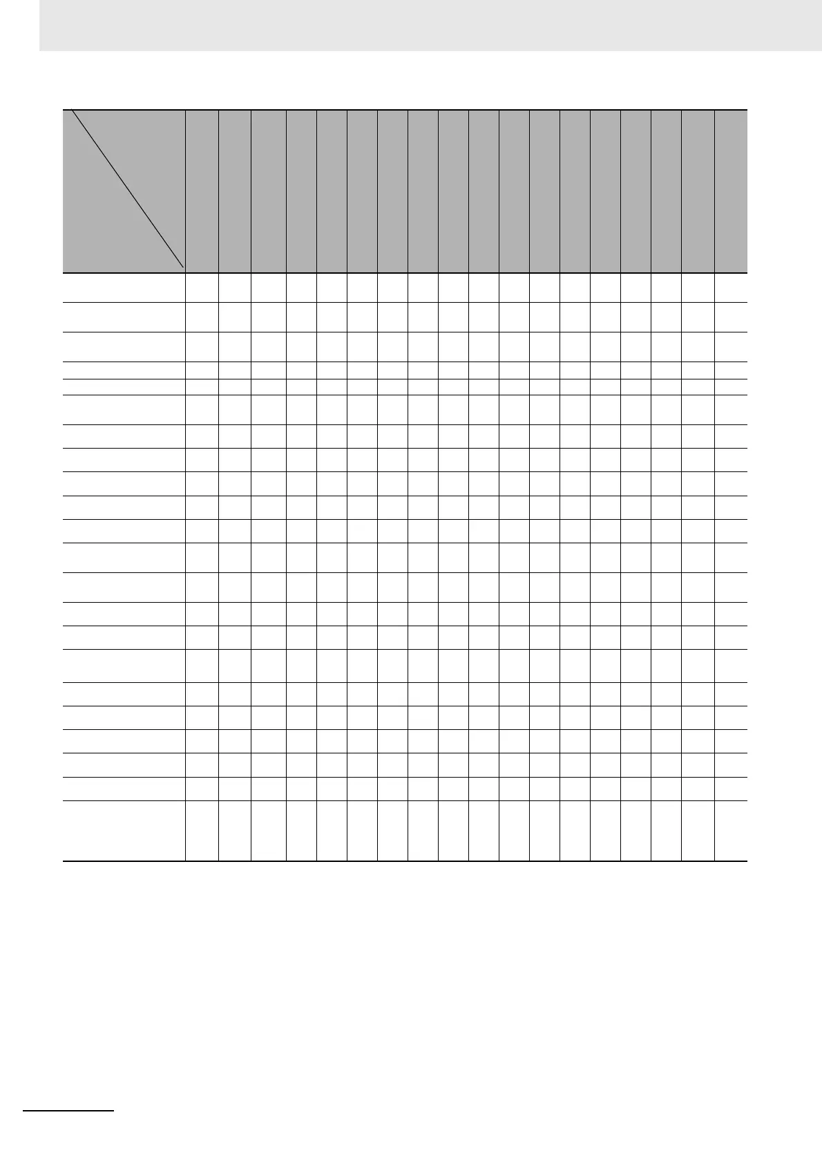
*1 Initialized to input setting range upper and lower limits, or scaling upper and lower limits.
*2 Clamped by SP upper and lower limits.
*3 This parameter is initialized only when the input type is changed to analog input when the RT parameter is ON. The RT
parameter turns OFF.
*4 Initialization is performed as shown below according to the transfer output type setting. The initialization differs
depending on the changed parameter and the output type setting.
• SP: SP upper and lower limits
• Ramp SP: SP upper and lower limits
• PV: Input setting range upper and lower limits or scaling upper and lower limits
• MV (Heating): 100.0/0.0
• MV (Cooling): 100.0/0.0
• Valve opening: 100.0/0.0
*4.1 Initialized only when the transfer output type is set to SP, Ramp SP, or PV.
*4.2 Initialized only when the transfer output type is set to MV (Heating) or MV (Cooling).
Auxiliary Output 3
Assignment
--- --- --- --- --- ●●--- --- --- --- --- --- --- --- --- --- ---
Auxiliary Output 4
Assignment
--- --- --- --- ---
●
*6
●
*6
--- --- --- --- --- --- --- --- --- --- ---
Event Input
Assignment 1 to 6
--- --- --- --- --- ---
●
*8
--- --- --- --- --- --- --- --- --- --- ---
Move to Protect Level
--- --- --- --- --- --- --- --- --- --- --- --- --- --- ---
●
*10
--- ---
MV Display Selection
--- --- --- --- --- ● --- --- --- --- --- --- --- --- --- --- --- ---
Position Proportional
Dead Band
--- --- --- --- --- --- --- --- --- --- --- --- --- --- --- ---
●
*20
---
Dead Band
●
*13
●
*23
--- --- --- --- --- --- --- --- --- --- --- --- --- --- --- ---
Hysteresis (Heating)
●
*13
●
*23
--- --- --- --- --- --- --- --- --- --- --- --- --- --- --- ---
Hysteresis (Cooling)
●
*13
●
*23
--- --- --- --- --- --- --- --- --- --- --- --- --- --- --- ---
Wait Band
●
*13
●
*23
--- --- --- --- --- --- --- --- --- --- --- --- --- --- --- ---
Alarm Values 1 to 4
--- ●
*23
--- --- --- --- --- --- --- --- --- --- --- --- --- --- --- ---
Alarm Upper Values 1
to 4
--- ●
*23
--- --- --- --- --- --- --- --- --- --- --- --- --- --- --- ---
Alarm Lower Values 1
to 4
--- ●
*23
--- --- --- --- --- --- --- --- --- --- --- --- --- --- --- ---
Alarm 1 to 4 Hysteresis
●
*14
●
*23
--- --- --- --- --- --- --- --- --- --- ---
●
*15
--- --- --- ---
ST Stable Range
●
*13
●
*23
--- --- --- --- --- --- --- --- --- --- --- --- --- --- --- ---
AT Hysteresis
●
*13
*18
●
*18
*23
--- --- --- --- --- --- --- --- --- --- --- --- --- --- --- ---
LBA Level
●
*13
●
*23
--- --- --- --- --- --- --- --- --- --- --- --- --- --- --- ---
LBA Band
●
*13
●
*23
--- --- --- --- --- --- --- --- --- --- --- --- --- --- --- ---
SP Ramp Set Value
--- ●
*23
--- --- --- --- --- --- --- --- --- --- --- --- --- --- --- ---
SP Ramp Fall Value
--- ●
*23
--- --- --- --- --- --- --- --- --- --- --- --- --- --- --- ---
SP Offset
--- ●
*23
--- --- --- --- --- --- --- --- --- --- --- --- --- --- --- ---
Simple Transfer Output
1 Upper Limit and
Simple Transfer Output
1 Lower Limit
*22
●
*22.1
●
*22.1
*23
●
*22.1
●
*22.1
--- ●
*22.2
--- --- --- --- ●
*22.3
--- --- --- --- --- --- ---
Input Type
Temperature Unit
Scaling Lower Limit
Scaling Upper Limit
SP Lower Limit
SP Upper Limit
PID ON/OFF
Standard or
Heating/Cooling
Program Pattern
ST
Remote SP Enable
Transfer Output Type
Control Output 1 Assignment
RT
Integral/Derivative Time Unit
Alarm 1 to 4 Type
SP 0 to 7
Set Point
Password to Move to
Protect Level
Close/Floating
Direct Setting of Position
Proportional MV
Related
initialized
parameters
Changed
parameter

 Loading...


