6 Programless Communications
6 - 50
E5@C Digital Temperature Controllers Communications Manual (H175)
Before you attach the CJ1W-CIF11 to the CJ1W-SCU22, turn OFF pin 4 on the DIP switch on the back
of the CJ1W-CIF11 and turn ON the rest of the pins.
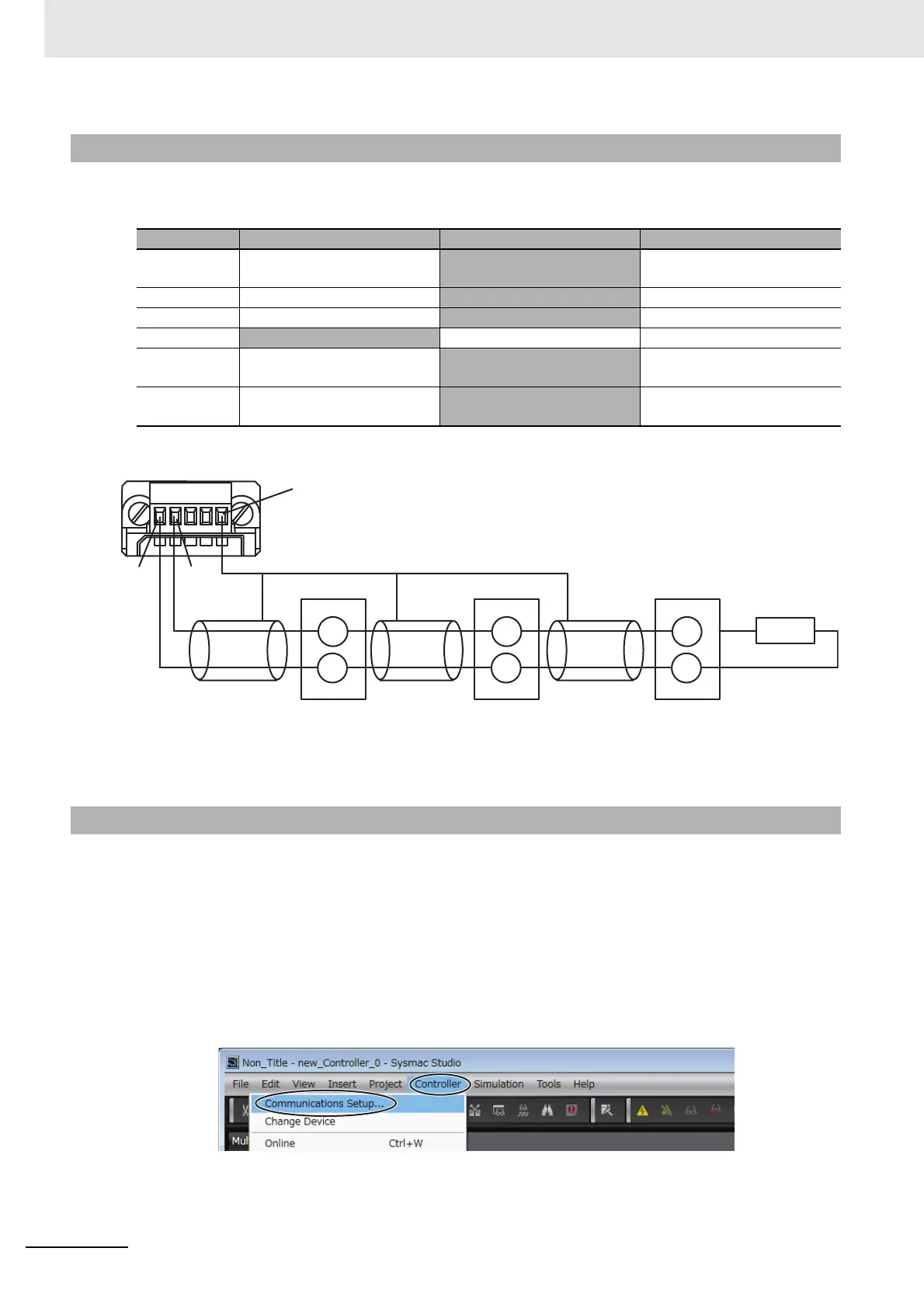
Wire the CJ1W-CIF11 to the E5CC Controllers as shown below.
Note: 1 The maximum transmission distance is 50 m.
2 For wiring methods, refer to Appendix G CJ1W-CIF11 RS-422A Converter in the SYSMAC CJ series
Programmable Controller Operation Manual (Cat. No. W393).
Set up communications on the CJ1W-SCU22 to enable communicating with the E5CC Controllers.
PLC operation will stop during the setup procedure. Make sure that this will not create any problems in
the controlled system.
Connecting to the PLC
(1) Connect the computer to the NJ101-1000 with a USB cable and then start the Sysmac
Studio.
(2) Select Controller − Communications Setup from the menu bar.
6-7-2 Switch Settings and Wiring
Pin No. OFF ON Setting
1None Terminating resistance on
both ends
Terminating resistance
selection
2 4-wire 2-wire 2-wire or 4-wire selection
3 4-wire
2-wire Same as above.
4 --- --- Spare
5 RS control disabled. (Signal
always received.)
RS control enabled. RS control selection for RD
6 RS control disabled. (Signal
always sent.)
RS control enabled. RS control selection for SD
6-7-3 PLC Setup
13
14
13
14
13
14
FG
CJ1W-CIF11
RDB+
RDA-
Shield
B(+)
A(−)
E5CC
No.0
Shield
B(+)
A(−)
E5CC
No.1
Shield
B(+)
A(−)
E5CC
No.2
Terminating resistance
120 Ω (1/2 W)

 Loading...


