6 - 87
6 Programless Communications
E5@C Digital Temperature Controllers Communications Manual (H175)
6-11 Connecting to Keyence KV-series PLCs
6
6-11-1 Configuration and Procedure
6-11 Connecting to Keyence KV-series
PLCs
This function is supported only for E5@C version 2.1 or later.
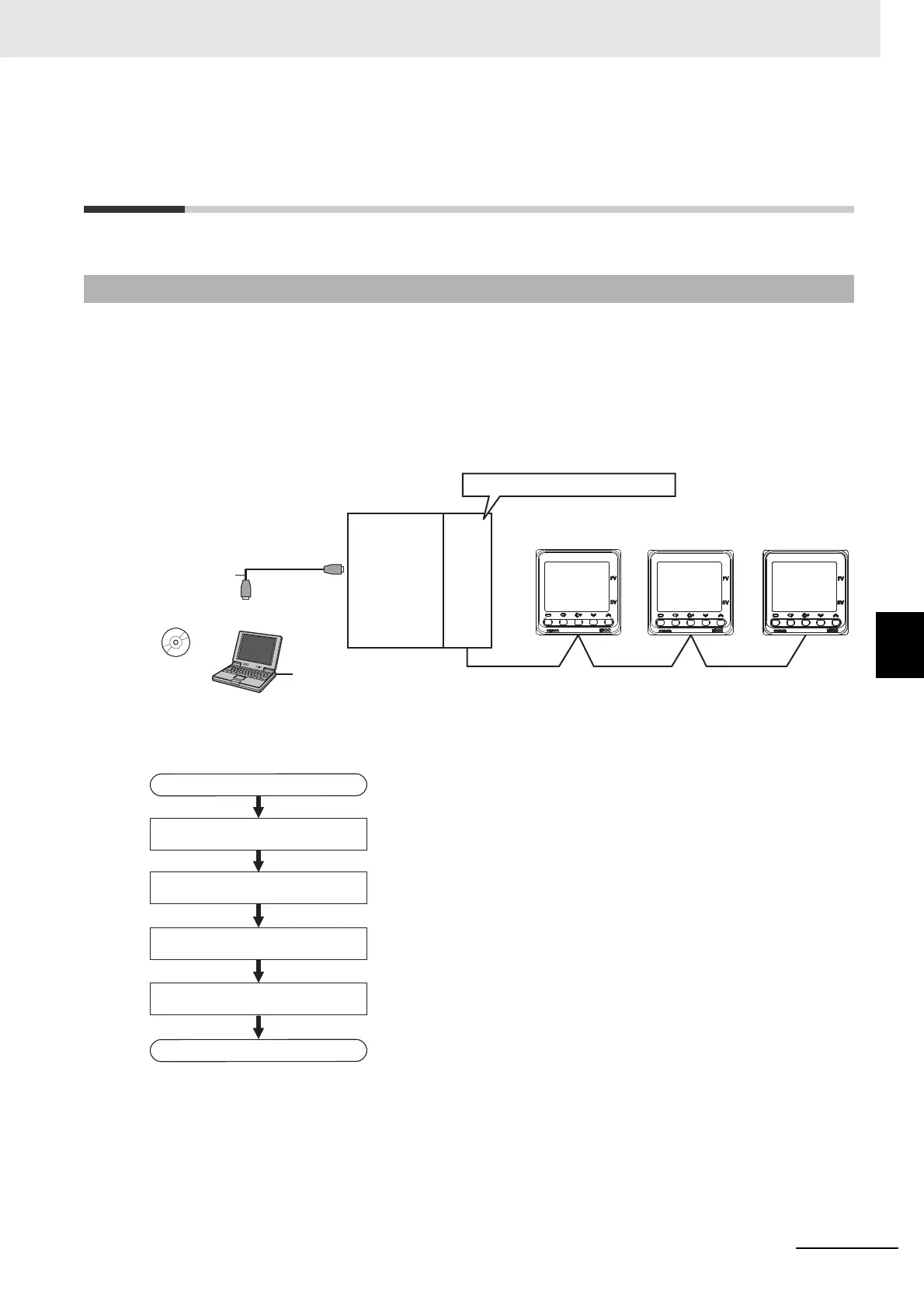
The following configuration is used as an example in giving the setup and application procedures for
programless communications.
• All of the E5CC Controllers must be the same model. (Copying parameter settings is not possible if
the models are different.)
• DM0 to DM89 are used in the PLC memory. The default E5CC parameter allocations are used.
• A commercially available USB2.0, A/B cable is used.
Note: Refer to the KV STUDIO User’s Manual for the installation procedures for the KV STUDIO and USB driver.
The application procedure is given below.
6-11-1 Configuration and Procedure
25
0
C
0
C
25
0
C
E5CC
No.0
E5CC
No.1
E5CC
No.2
25
RS-485
KV STUDIO
Programming
Software
Turn ON the terminating resistance switch.
KV- 700 KV-L21V
USB port
IBM PC/AT or compatible
Commercially
available USB
cable
START
Wire the network.
Wire the KV-L21V to the E5CC Controllers.
Set up the E5@C Controllers. Set up programless communications in the E5CC Controllers.
Check operation. Use the KV STUDIO to confirm that programless communications are operating.
Set up the PLC. Use KV STUDIO to set up communications on the KV-L21V to enable
communicating with the E5CC Controllers.
END

 Loading...


