2 CompoWay/F Communications Procedures
2 - 6
E5@C Digital Temperature Controllers Communications Manual (H175)
2-2 Structure of Command Text
An MRC (Main Request Code) and SRC (Sub-Request Code) followed by the various required data is
transferred to the command text.
• Service Request PDU
The MRES (Main Response Code) and SRES (Sub-Response Code) are transferred to the
response frame following the above MRC/SRC. Data is then transferred following the MRES and
SRES.
• Service Response PDU (Normal Response)
If the specified command text could not be executed, the service response PDU will contain only the
MRC/SRC and MRES/SRES.
• Service Response PDU (Command Text Not Executed)
MRES/SRES provides the response code. MRES/SRES are not output when processing ends in a
normal completion.
Areas comprise only the variable area.
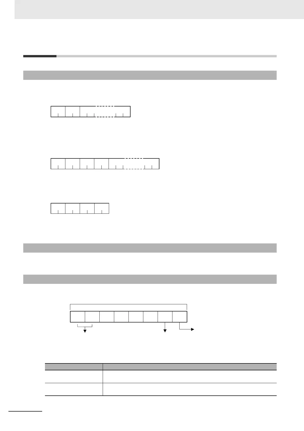
The following figure shows the variable area type code.
The following table summarizes setup areas 0 and 1.
The type code depends on the parameter. Refer to 3-1 Variable Area (Setting Range) List for details.
2-2-1 PDU Structure
2-2-2 Area Definitions
2-2-3 Type Code (Variable Type)
Area Description
Setup area 0 This area groups together the protect, manual control, operation, and adjustment
levels.
Setup area 1 This area groups together the initial setting, communications setting, advanced
function setting, and calibration levels.
0000
LSBMSB
Variable type (1 byte)
Access size
11: Double word
10: Word
Area
0: Setup area 0
1: Setup area 1
Read/Write
0: Read only
1: Read/Write

 Loading...


