6 - 67
6 Programless Communications
E5@C Digital Temperature Controllers Communications Manual (H175)
6-9 Connecting to MELSEC-FX-series PLCs
6
6-9-2 Wiring
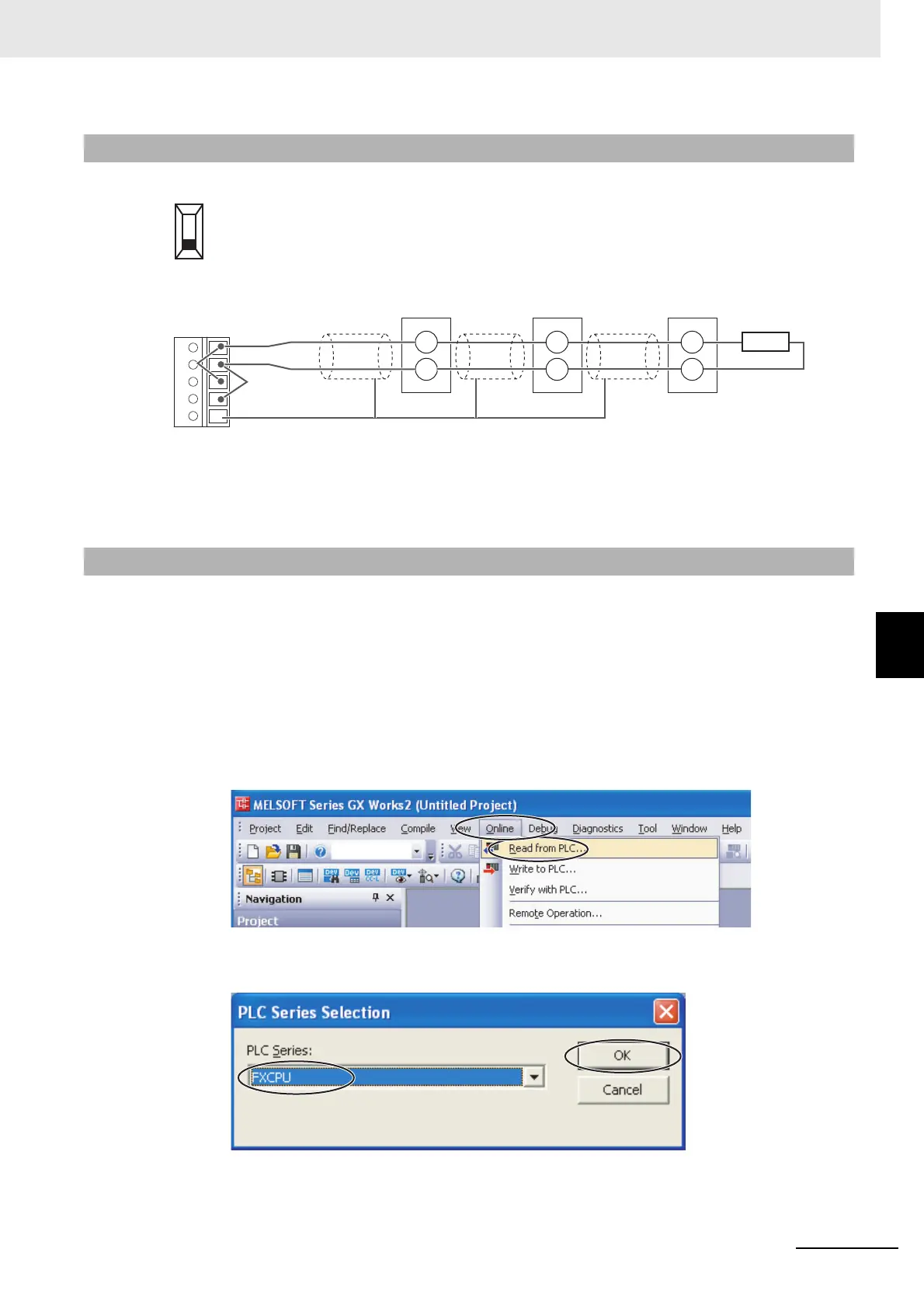
Set the terminating resistance switch on the front panel of the FX3U-485ADP-MB to 110 Ω.
Wire the FX3U-485ADP-MB to the E5CC Controllers as shown below.
Note: 1 Use a terminating resistance of at least 54 Ω.
2 The maximum transmission distance is 500 m.
3 For wiring methods, refer to 4.5.1 One-pair wiring under D.Computer Link in the FX Series User’s Manual,
Data Communication Edition (JY997D16901).
Set up communications on the FX3U-485ADP-MB to enable communicating with the E5CC Controllers.
PLC operation will stop and the power supply will be cycled during the setup procedure. Make sure that
this will not create any problems in the controlled system.
Connecting to the PLC
(1) Connect the computer to the FX-series CPU Module with a USB cable and then start
GX Works2.
(2) Select Online
−
Read from PLC from the menu bar.
(3) Select FXCPU, and then click the OK Button.
6-9-2 Wiring
6-9-3 PLC Setup
FX3U-485ADP-MB
SDA
SDB
RDA
RDB
SG
Shield Shield Shield
13
14
E5CC
No.0
E5CC
No.1
E5CC
No.2
B(+)
A(
−)
13
14
B(+)
A(
−)
13
14
B(+)
A(
−)
120 Ω (1/2 W)
terminating resistance

 Loading...


