4 - 11
4 Modbus Communications Procedure
E5@C Digital Temperature Controllers Communications Manual (H175)
4-4 Detailed Description of the Functions
4
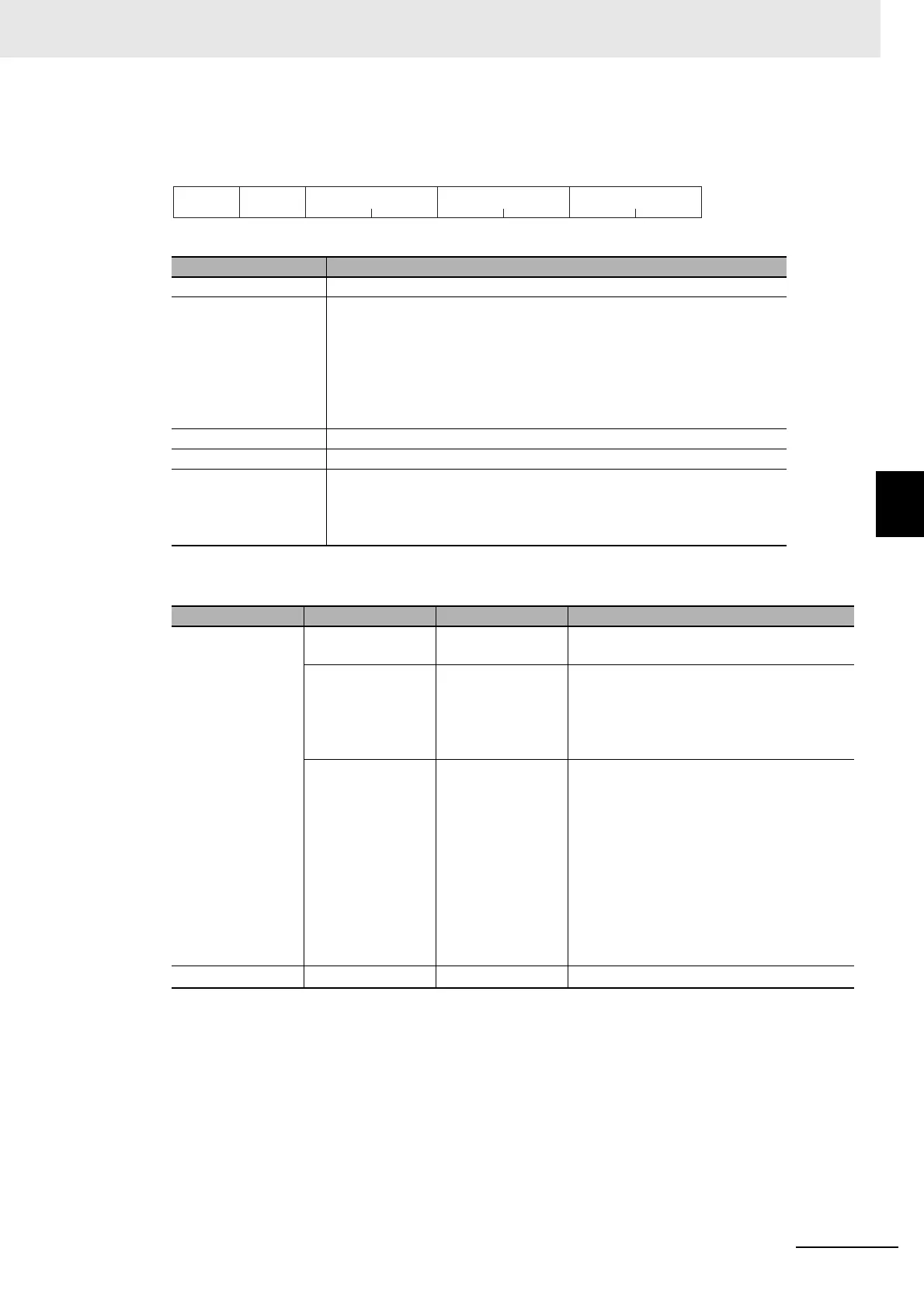
4-4-2 Variable Write, Multiple
Response Frame
Response Code
Name Description
Slave address The value from the command frame is entered as-is.
Function code This is the received function code.
When the function ended normally, the function code is left as-is. When
an error occurred, the hexadecimal value of H'80 is added to the function
code to indicate that the response is an error response.
Example: Received function code = H'10
Function code in response frame when an error occurred =
H'90
Write start address This is the received write start address.
Number of elements This is the received number of elements.
CRC-16 This check code is calculated with the data from the slave address to the
end of the data.
For details on the CRC-16 calculation, refer to CRC-16 Calculation
Example in 4-1-1 Command Frame on page 4-2.
Function code Error code Error name Cause
H'90 H'02
Variable address
error
The write start address is incorrect.
H'03
Variable data error • The amount of data does not match the
number of elements.
• The byte count is not 2 times the number
of elements.
• The write data is out of the setting range.
H
'04
Operation error The Controller cannot write the data in its
present operating status.
The write data contents are not allowed in
the present operation mode.
• The Communications Writing parameter is
set to "OFF" (disabled).
• Attempted to write to a parameter in setup
area 1 from setup area 0.
• Attempted to write to a protect parameter
from other than the protect level.
• AT execution is in progress.
H
'10
--- Normal completion No errors were found.
CRC-16
12
2
1
H’ 10
Number of
Elements
2 bytes
Slave
address
Function
code
Write start address

 Loading...


