3 - 25
3 Communications Data for CompoWay/F
E5@C Digital Temperature Controllers Communications Manual (H175)
3-2 Status and Status 2
3
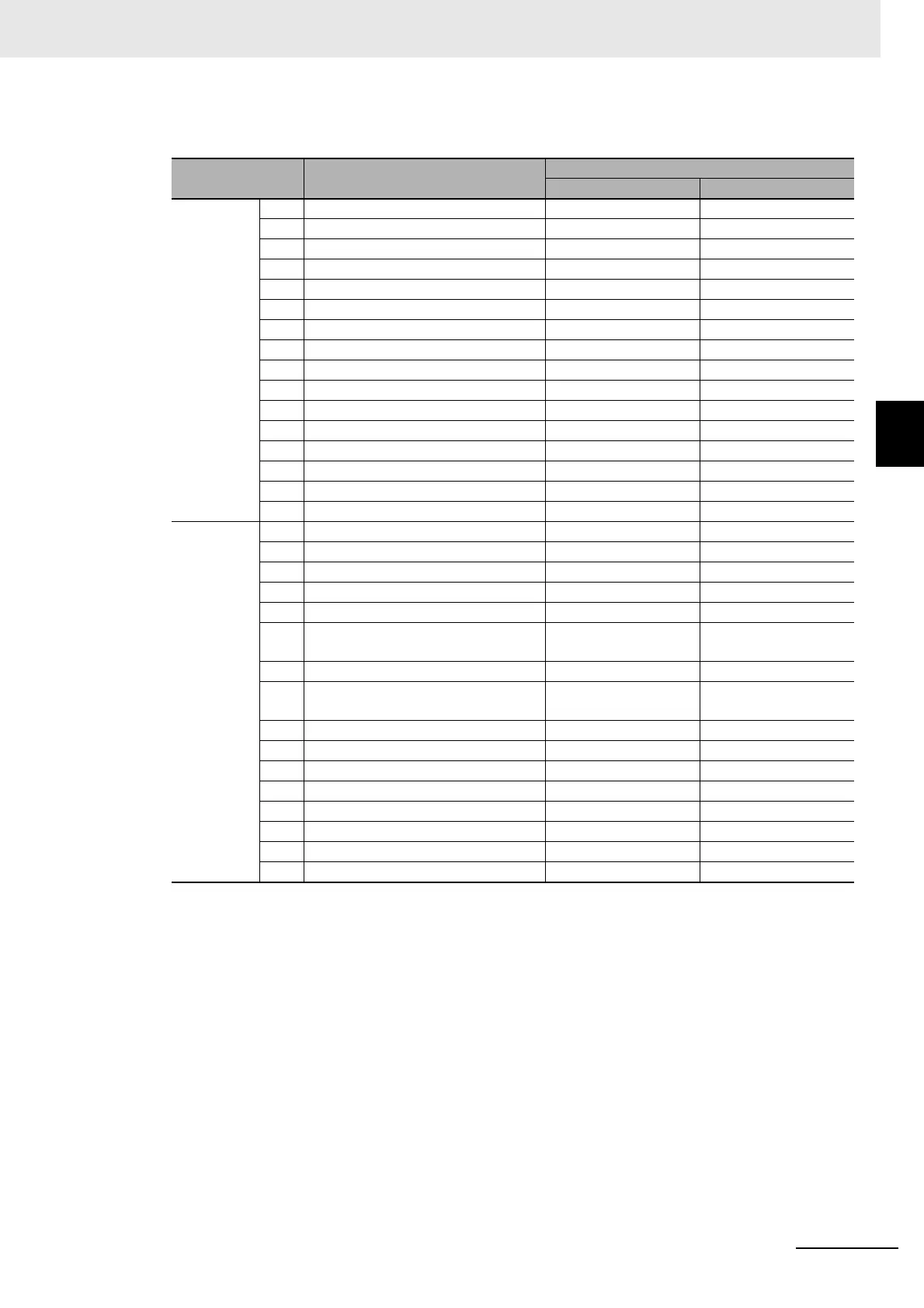
Status Details
Note1 “Spare” bits are always OFF.
2 When read in setup area 1, the status of the bits will be as follows:
* When the control output ON time is less than 30 ms for a control period of 0.1 s or 0.2 s or when it is less than
100 ms for any other control period, the bit is set to “1” and the heater current is held at the last current value.
Bit position Status
Bit Description
0 1
Status
(lower
word)
0 Heater overcurrent (CT1) Not generated Generated
1 Heater current hold (CT1)* Update Hold
2 A/D converter error Not generated Generated
3 HS alarm (CT1) OFF ON
4 RSP input error Not generated Generated
5 Spare OFF ---
6 Input error Not generated Generated
7 Potentiometer input error Not generated Generated
8 Control output (heating)/open output OFF ON
9 Control output (cooling)/close output OFF ON
10 HB (heater burnout) alarm (CT1) OFF ON
11 HB (heater burnout) alarm (CT2) OFF ON
12 Alarm 1 OFF ON
13 Alarm 2 OFF ON
14 Alarm 3 OFF ON
15 Program end output OFF ON
Status
(upper
word)
16 Event input 1 OFF ON
17 Event input 2 OFF ON
18 Event input 3 OFF ON
19 Event input 4 OFF ON
20 Write mode Backup mode RAM write mode
21 Non-volatile memory RAM = Non-volatile
memory
RAM ≠ Non-volatile
memory
22 Setup area Setup area 0 Setup area 1
23 AT execute/cancel AT canceled AT execution in
progress
24 RUN/STOP Run Stop
25 Communications writing OFF (disabled) ON (enabled)
26 Auto/manual switch Automatic mode Manual mode
27 Program start Reset Start
28 Heater overcurrent (CT2) Not generated Generated
29 Heater current hold (CT2) Update Hold
30 Spare OFF ---
31 HS alarm (CT2) OFF ON
• Overcurrent: Last value held
• A/D converter error: Last value held
• Input error: Last value held
• HB and HS outputs: Cleared
• Program end output: Cleared
• Current hold: Last value held
• Heating and cooling outputs: Cleared
• Alarm outputs: Cleared

 Loading...


