4-7
4 Installation and Wiring
NJ-series CPU Unit Hardware User’s Manual (W500)
4-2 Fail-safe Circuits
4
4-2-1 Order of Powering Up the Controller and Controlled System
Outputs from Units, such as DC Output Units, may malfunction momentarily when the power to the
Controller is turned ON. This may cause problems in the system if the Controller power supply is turned
ON after the controlled system's power supply. To prevent possible malfunctions, add an external circuit
that prevents the power supply to the controlled system from going ON before the power supply to the
Controller itself.
It takes approximately 10 to 20 s to enter RUN mode after the power supply is turned ON. During
that time, outputs will be OFF or the values will be according to settings in the Units or slaves.
Also, external communications cannot be performed. Use the RUN output on the Power Supply
Unit, for example, to implement fail-safe circuits so that external devices do not operate incor-
rectly.
It is possible for an output to remain ON due to a malfunction in the internal circuitry of the Output Unit,
such as a relay or transistor malfunction. Be sure to add any circuits necessary outside of the Controller
to ensure the safety of the system in the event that an output fails to go OFF.
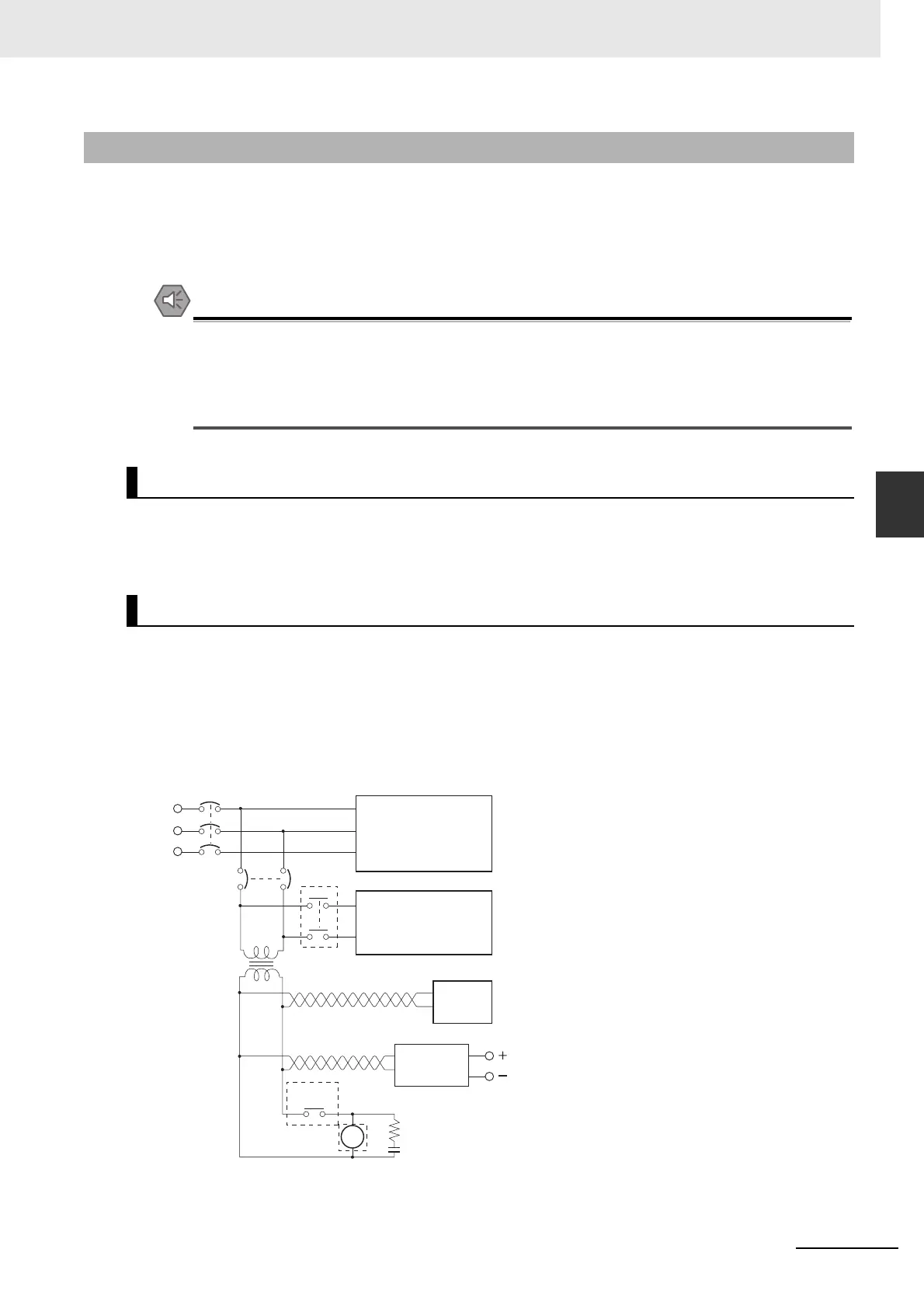
The following emergency stop circuit controls the power supply to the controlled system so that power
is supplied to the controlled system only when the Controller is operating and the RUN output is ON. An
external relay (CR1) is connected to the RUN output from the Power Supply Unit* as shown in the fol-
lowing diagram.
* A RUN output is provided only on the NJ-PA3001/-PD3001 Power Supply Unit.
Electrical Diagram
4-2-1 Order of Powering Up the Controller and Controlled System
Output Unit Failure
Power Supply Wiring and Emergency Stop Circuit
MCB1
MCB2
CR1
CR1
DC
Controller RUN
output
input/output
Power supply
Controlled system
DC voltage
regulator
Surge suppressor
Twisted-pair wires
Transformer
or noise filter
NJ-series
Controller

 Loading...


