Appendices
A-100
NJ-series CPU Unit Hardware User’s Manual (W500)
A-5 EMC Directive Measures for Relay
Outputs
The NJ-series Controllers conform to the Common Emission Standards (EN 61131-2) of the EMC
Directives. However, noise generated by relay output switching may not satisfy these Standards when
the Controller is incorporated into a system. In such a case, a noise filter must be connected to the load
side or other appropriate countermeasures must be provided external to the Controller.
Countermeasures taken to satisfy the standards vary depending on the devices on the load side, wir-
ing, configuration of machines, etc. Following are examples of countermeasures for reducing the gen-
erated noise.
Countermeasures
(Refer to EN61131-2 for more details.)
Countermeasures are not required if the frequency of load switching for the whole system with the
Controller included is less than 5 times per minute.
Countermeasures are required if the frequency of load switching for the whole system with the Con-
troller included is 5 times or more per minute.
Countermeasure Examples
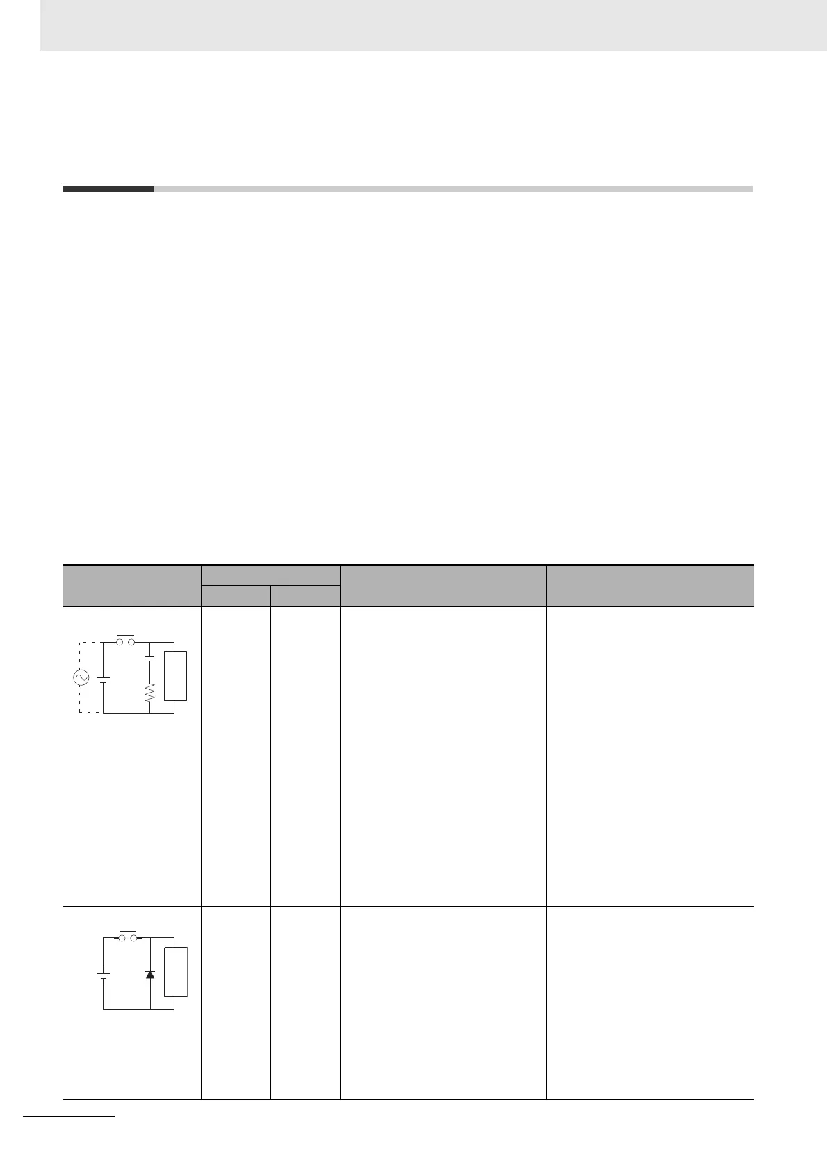
When switching an inductive load, connect an surge protector, diodes, etc., in parallel with the load
or contact as shown below.
Circuit
Current
Characteristic Required element
AC DC
Yes Yes If the load is a relay or solenoid,
there is a delay in the resetting
time.
If the supply voltage is 24 or 48 V,
insert the surge protector in parallel
with the load. If the supply voltage
is 100 to 200 V, insert the surge
protector between the contacts.
The capacitance of the capacitor
should be approx. 1 to 0.5 F per
contact current of 1 A and resis-
tance of the resistor should be
approx. 0.5 to 1 per contact volt-
age of 1 V. These values, however,
vary with the load and the charac-
teristics of the relay. Decide these
values from experiments, and take
into consideration that the capaci-
tance suppresses spark discharge
when the contacts are separated
and the resistance limits the current
that flows into the load when the
circuit is closed again.
The dielectric strength of the
capacitor must be 200 to 300 V. If
the circuit is an AC circuit, use a
capacitor with no polarity.
No Yes The diode connected in parallel
with the load changes energy accu-
mulated by the coil into a current,
which then flows into the coil so
that the current will be converted
into Joule heat by the resistance of
the inductive load.
This delay in the resetting time,
caused by this method is longer
than that caused by the CR
method.
The reversed dielectric strength
value of the diode must be at least
10 times as large as the circuit volt-
age value. The forward current of
the diode must be the same as or
larger than the load current.
The reversed dielectric strength
value of the diode may be two to
three times larger than the supply
voltage if the surge protector is
applied to electronic circuits with
low circuit voltages.
CR method
Power
supply
Inductive
load
C
R
Diode method
Power
supply
Inductive
load

 Loading...


