2-5
2 System Configuration
NJ-series CPU Unit Hardware User’s Manual (W500)
2-1 Basic System Configuration
2
2-1-2 CJ-series Unit Configuration
The CJ-series Unit configuration consists of the CJ-series Units that are connected. It includes the CJ-
series Units on the CPU Rack and Expansion Racks.
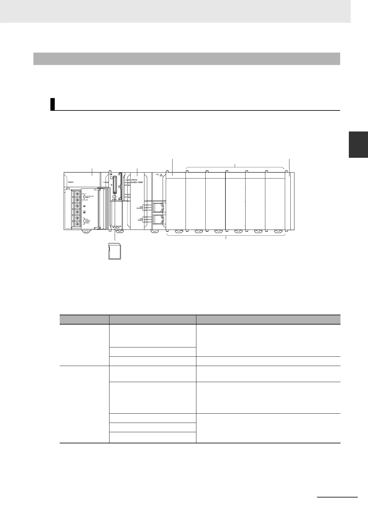
The CPU Rack consists of an NJ-series CPU Unit, an NJ-series Power Supply Unit, CJ-series
Configuration Units, and a CJ-series End Cover. Up to 10 CJ-series Configuration Units can be con-
nected.
* The I/O Control Unit is required only to connect an Expansion Rack. It must be connected immediately to the
right of the CPU Unit.
Even though the NJ-series Controllers do not have Backplanes, the term “slot” is still used to refer to
the location of Units. Slot numbers are assigned in order to Units from left to right on the CPU Rack (slot
0, slot 1, slot 2, etc.).
2-1-2 CJ-series Unit Configuration
CPU Rack
Name Configuration Remarks
NJ-series Units NJ-series CPU Units (One End
Cover is provided with each
Unit.)
One required for every CPU Rack.
NJ-series Power Supply Unit
SD Memory Card Install as required.
CJ-series Units I/O Control Unit Required to connect an Expansion Rack. Must be con-
nected immediately to the right of the CPU Unit.
End Cover Must be connected to the right end of the CPU Rack.
One End Cover is provided with the CPU Unit.
(A Controller error in the major fault level will occur if the
End Cover is not connected to the right end.)
CJ-series Basic I/O Units A total of up to 10 Units can be connected to the CPU
Rack and to each of the Expansion Racks. (A Controller
error in the major fault level will occur if 11 or more Units
are connected.)
CJ-series Special I/O Units
CJ-series CPU Bus Units
NJ-series
CPU Unit
CJ-series Configuration Units
(10 Units max.)
NJ-series Power
Supply Unit
SD Memory Card
End Cover
I/O Control Unit
*
Configuration Units

 Loading...


