4 Installation and Wiring
4-40
NJ-series CPU Unit Hardware User’s Manual (W500)
AC Input Units
Precautions for Correct UsePrecautions for Correct Use
When using a reed switch as the input contact for an AC Input Unit, use a switch with an allow-
able current of 1 A or greater. If reed switches with smaller allowable currents are used, the con-
tacts may fuse due to surge currents.
Precautions when Connecting a Two-wire DC Sensor
When using a two-wire sensor with a 24-VDC input device, check that the following conditions have
been met. Failure to meet these conditions may result in operating errors.
(1) Relation between voltage when the Controller is ON and the sensor residual voltage:
V
ON VCC VR
(2) Relation between voltage when the Controller is ON and sensor control output (load
current):
I
OUT (min) ION IOUT (max.)
I
ON = (VCC VR 1.5 [Controller internal residual voltage])/RIN
When ION is smaller than IOUT (min), connect a bleeder resistor R. The bleeder resistor con-
stant can be calculated as follows:
R (V
CC VR)/(IOUT (min.) ION)
Power W (V
CC VR)
2
/R 4 [allowable margin]
V
CC: ON voltage to Input Unit
V
R: Sensor output residual current
I
ON: Input Unit ON current
I
OUT: Sensor control current (load current)
R
IN: Input Unit input impedance
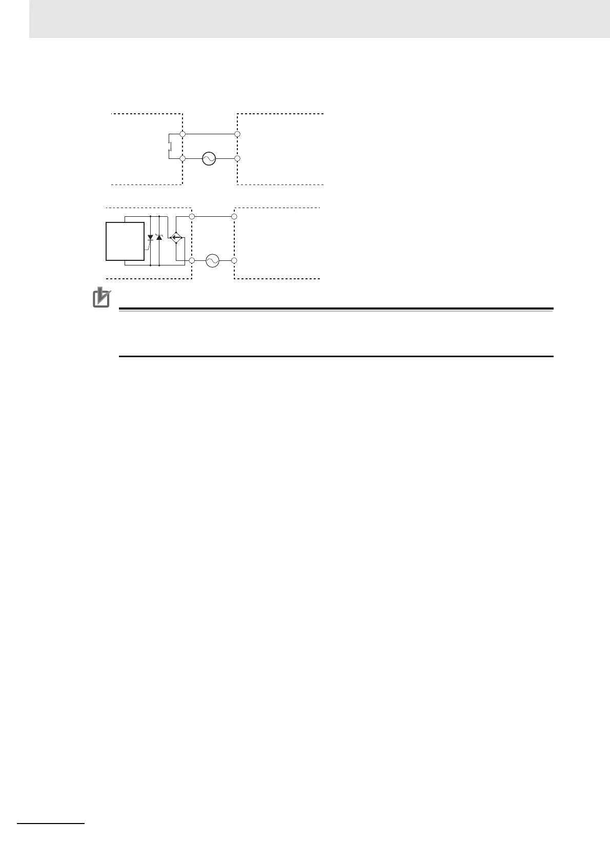
COM
IN
AC Input Unit
Contact output
AC Switching
Proximity
switch
main
circuit
COM
IN
AC Input Unit

 Loading...


