Appendices
A-44
NJ-series CPU Unit Hardware User’s Manual (W500)
* The ON response time will be 20 s maximum and OFF response time will be 400 s maximum even if the response times
are set to 0 ms due to internal element delays.
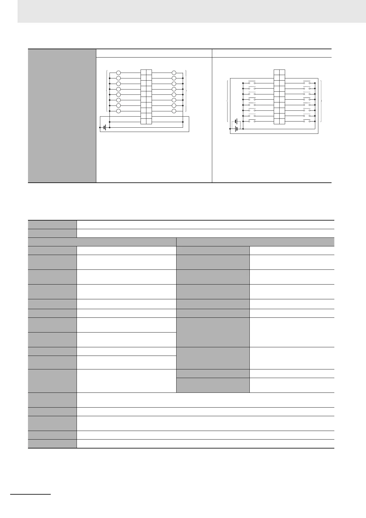
CJ1W-MD261 DC Input/Transistor Output Unit (24 VDC 32 Inputs/32 Outputs)
External connection and
terminal-device variable
diagram
CN1 (OUT) CN2 (IN)
• When wiring, pay careful attention to the polarity
of the external power supply. The load may oper-
ate incorrectly if polarity is reversed.
• Be sure to wire both terminals 3 and 4 (COM0
(0 V)) of CN1.
• Be sure to wire both terminals 1 and 2 (+V) of
CN1.
• When wiring, pay careful attention to the polarity of
the external power supply. The load may operate
incorrectly if polarity is reversed.
• Be sure to wire both pins 3 and 4 (COM1) of CN2,
and set the same polarity for both pins.
Name 32-point DC Input/32-point Transistor Output Unit with Fujitsu Connectors (Sinking Outputs)
Model CJ1W-MD261
Output section (CN1) Input section (CN2)
Rated Voltage 12 to 24 VDC Rated Input Voltage 24 VDC
Operating Load
Voltage Range
10.2 to 26.4 VDC
Operating Input Voltage
20.4 to 26.4 VDC
Maximum Load
Current
0.3 A/point, 1.6 A/common, 3.2 A/Unit
Input Impedance
5.6 k
Maximum Inrush
Current
3.0 A/point, 10 ms max.
Input Current
4.1 mA typical (at 24 VDC)
Leakage Current
0.1 mA max.
ON Voltage/ON Current
19.0 VDC min./3 mA min.
*1
Residual Voltage 1.5 V max. OFF Voltage/OFF Current 5 VDC max./1 mA max.
ON Response
Time
0.5 ms max.
ON Response Time
8.0 ms max. (Can be set to between
0 and 32 ms in the Unit Information
settings.)
*2
OFF Response
Time
1.0 ms max.
No. of Circuits 32 (16 points/common, 2 circuits)
OFF Response Time
8.0 ms max. (Can be set to between
0 and 32 ms in the Unit Information
settings.)
*2
Fuse
None
External Power
Supply
12 to 24 VDC, 30 mA min.
No. of Circuits 32 (16 points/common, 2 circuits)
Number of Simultaneously
ON Points
75% (24 points) (at 24 VDC)
Insulation Resis-
tance
20 M between the external terminals and the GR terminal (at 100 VDC)
Dielectric Strength 1,000 VAC between the external terminals and the GR terminal for 1 minute at a leakage current of 10 mA max.
Internal Current
Consumption
5 VDC 140 mA max.
Weight 110 g max.
Accessories None
12 to
24 VDC
Wd m
Wd m
Signal
name
Signal
name
Connec-
tor pin
Allocated
CIO word
Allocated
CIO word
1
3
5
7
9
11
13
15
17
19
2
4
6
8
10
12
14
16
18
20
L
L
L
L
L
L
L
L
L
L
L
L
L
L
L
L
Jxx_Ch1_Out00
Jxx_Ch1_Out01
Jxx_Ch1_Out02
Jxx_Ch1_Out03
Jxx_Ch1_Out04
Jxx_Ch1_Out05
Jxx_Ch1_Out06
Jxx_Ch1_Out07
Jxx_Ch1_Out08
Jxx_Ch1_Out09
Jxx_Ch1_Out10
Jxx_Ch1_Out11
Jxx_Ch1_Out12
Jxx_Ch1_Out13
Jxx_Ch1_Out14
Jxx_Ch1_Out15
COM0 (0 V)
+V
COM0 (0 V)
+V
24 VDC
Wd m+1
Wd m+1
Signal
name
Signal
name
Connec-
tor pin
Allocated
CIO word
Allocated
CIO word
20
18
16
14
12
10
8
6
4
2
19
17
15
13
11
9
7
5
3
1
Jxx_Ch1_In15
Jxx_Ch1_In14
Jxx_Ch1_In13
Jxx_Ch1_In12
Jxx_Ch1_In11
Jxx_Ch1_In10
Jxx_Ch1_In09
Jxx_Ch1_In08
Jxx_Ch1_In07
Jxx_Ch1_In06
Jxx_Ch1_In05
Jxx_Ch1_In04
Jxx_Ch1_In03
Jxx_Ch1_In02
Jxx_Ch1_In01
Jxx_Ch1_In00
COM1
NC
COM1
NC

 Loading...


