Appendices
A-46
NJ-series CPU Unit Hardware User’s Manual (W500)
CJ1W-MD263 DC Input/Transistor Output Unit (24 VDC 32 Inputs/32 Outputs)
Name 32-point DC Input/32-point Transistor Output Unit with MIL Connectors (Sinking Outputs)
Model CJ1W-MD263
Output section (CN1) Input section (CN2)
Rated Voltage 12 to 24 VDC Rated Input Voltage 24 VDC
Operating Load
Voltage Range
10.2 to 26.4 VDC
Operating Input Voltage
20.4 to 26.4 VDC
Maximum Load
Current
0.3 A/point, 1.6 A/common, 3.2 A/Unit
Input Impedance
5.6 k
Maximum Inrush
Current
3.0 A/point, 10 ms max.
Input Current
4.1 mA typical (at 24 VDC)
Leakage Current
0.1 mA max.
ON Voltage/ON Current
19.0 VDC min./3 mA min.
*1
Residual Voltage 1.5 V max. OFF Voltage/OFF Current 5 VDC max./1 mA max.
ON Response
Time
0.5 ms max.
ON Response Time
8.0 ms max. (Can be set to between 0
and 32 ms in the Unit Information set-
tings.)
*2
OFF Response
Time
1.0 ms max.
No. of Circuits 32 (16 points/common, 2 circuits)
OFF Response Time
8.0 ms max. (Can be set to between 0
and 32 ms in the Unit Information set-
tings.)
*2
Fuse
None
External Power
Supply
12 to 24 VDC, 30 mA min.
No. of Circuits 32 (16 points/common, 2 circuits)
Number of Simultane-
ously ON Points
75% (24 points) (at 24 VDC)
Insulation Resis-
tance
20 M between the external terminals and the GR terminal (at 100 VDC)
Dielectric Strength 1,000 VAC between the external terminals and the GR terminal for 1 minute at a leakage current of 10 mA max.
Internal Current
Consumption
5 VDC 140 mA max.
Weight 110 g max.
Accessories None
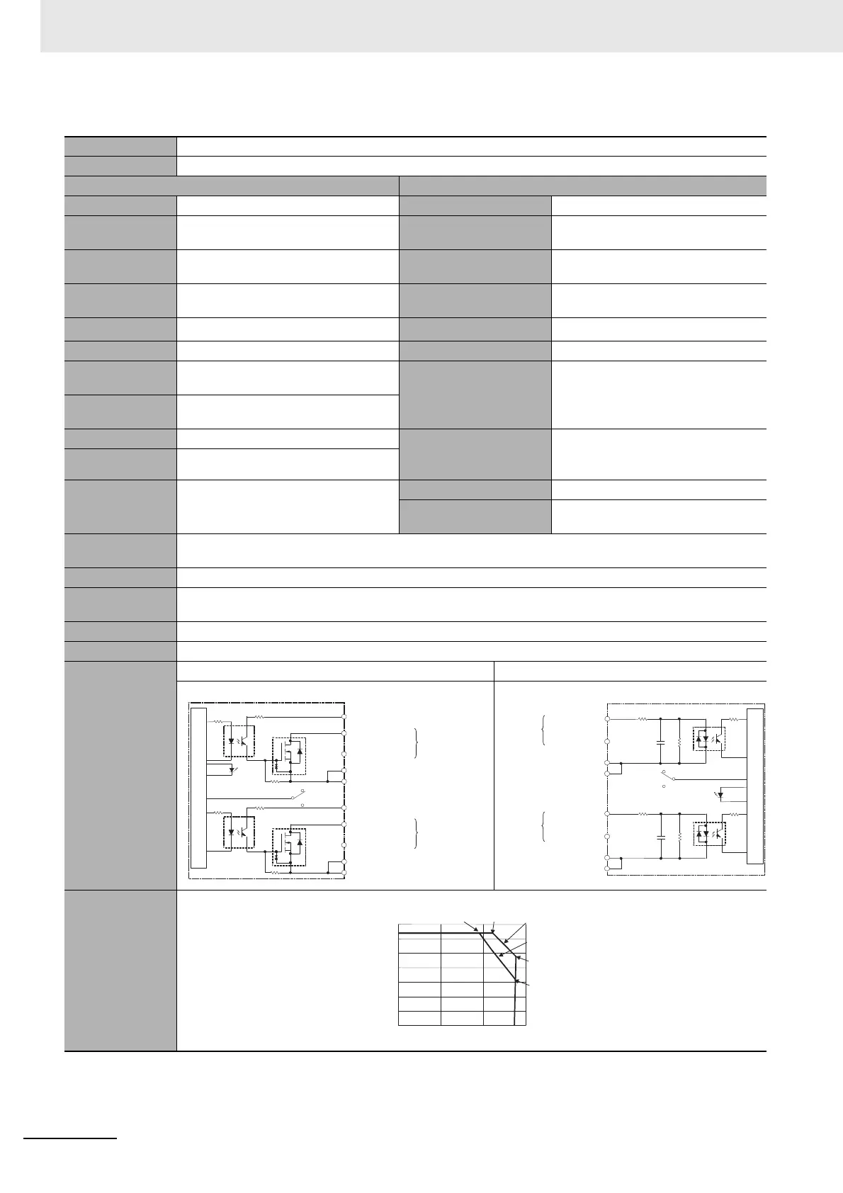
Circuit Configura-
tion
CN1 (OUT) CN2 (IN)
Internal circuits
Output
indicator
Indicator
switch
to
to
Wd m
Wd m+1
Allocated
CIO word
Signal
name
Jxx_Ch1_Out00
Jxx_Ch1_Out15
Jxx_Ch2_Out00
Jxx_Ch2_Out15
+V
+V
COM1
COM1
COM0
COM0
5.6 kΩ
560 Ω
1000 pF
5.6 kΩ
560 Ω
1000 pF
Internal circuits
Indicator switch
Input indicator
to
to
Wd m+2
Wd m+3
Allocated
CIO word
Signal
name
Jxx_Ch1_In00
Jxx_Ch1_In15
Jxx_Ch2_In00
Jxx_Ch2_In15
COM2
COM3
COM2
COM3
0
5
10
15
20
25
30
35
0 20 40 60
(°C)
No. of simultaneously ON inputs vs.
Ambient Temperature Characteristic
No. of simultaneously ON inputs
32 points at 38°C
32 points at 44°C
Ambient Temperature
Input voltage:
24 VDC
Input voltage:
26.4 VDC
12 points/
common
at 55°C
8 points/
common
at 55°C

 Loading...


