3 Configuration Units
3-4
NJ-series CPU Unit Hardware User’s Manual (W500)
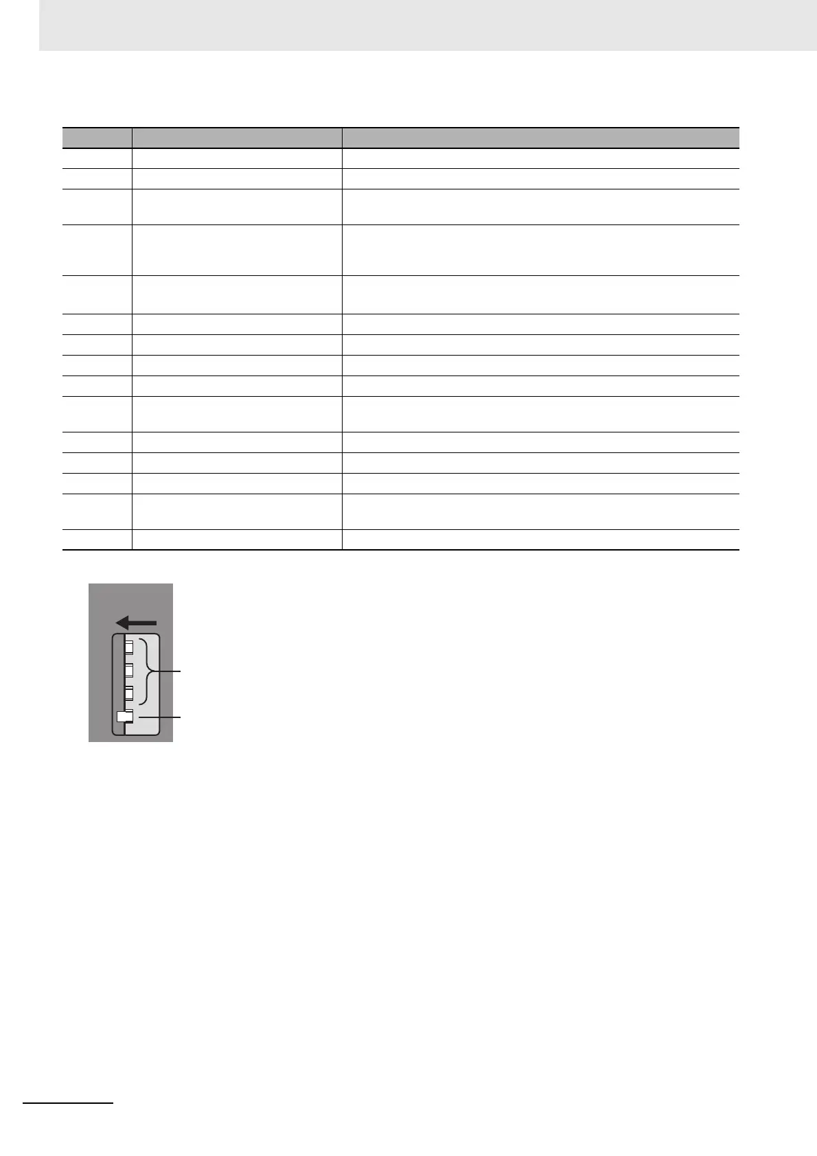
*1 To use Safe Mode, set the DIP switch as shown below and then turn ON the power supply to the Controller.
If the power supply to the Controller is turned ON with the CPU Unit in Safe Mode, the CPU Unit will start in PROGRAM
mode. Use the Safe Mode if you do not want to execute the user program when the power supply is turned ON or if it is
difficult to connect the Sysmac Studio.
Use the Safe Mode when it is difficult to connect the Sysmac Studio. For information on Safe Mode, refer to the NJ/NX-
series Troubleshooting Manual (Cat. No. W503).
*2 Refer to the NJ/NX-series CPU Unit Software User’s Manual (Cat. No. W501) for details on backing up data.
Number Name Function
1 Slider Holds the Units together.
2 SD Memory Card connector Connects the SD Memory Card to the CPU Unit.
3 CPU Unit operation indicators Shows the operation status of the CPU Unit.
Refer to CPU Unit Operation Status Indicators on page 3-5.
4 SD Memory Card power supply
switch
Turns OFF the power supply so that you can remove the SD Memory
Card.
Refer to 3-2 SD Memory Cards.
5 DIP switch
Used in Safe Mode
*1
or when backing up data.
*2
Normally, turn OFF all of the pins.
6 Battery connector Connector to mount the backup battery.
7 Battery Battery for backup.
8 Peripheral USB port Connects to the Sysmac Studio via a USB cable.
9 Built-in EtherNet/IP port (port 1) Connects the built-in EtherNet/IP with an Ethernet cable.
10 Built-in EtherNet/IP port operation
indicators
Shows the operation status of the built-in EtherNet/IP.
Refer to Built-in EtherNet/IP Port (Port 1) Indicators on page 3-7.
11 Unit connector Connects to another Unit.
12 ID information indication Shows the ID information of the CPU Unit.
13 Built-in EtherCAT port (port 2) Connects the built-in EtherCAT with an Ethernet cable.
14 Built-in EtherCAT port operation
indicators
Shows the operation status of the built-in EtherCAT.
Refer to Built-in EtherCAT Port (Port 2) Indicators on page 3-8.
15 DIN Track mounting pins Secures the Unit to a DIN Track.
ONON
1
2
3
4
Tu r n O F F.
Turn ON.

 Loading...


