4-88
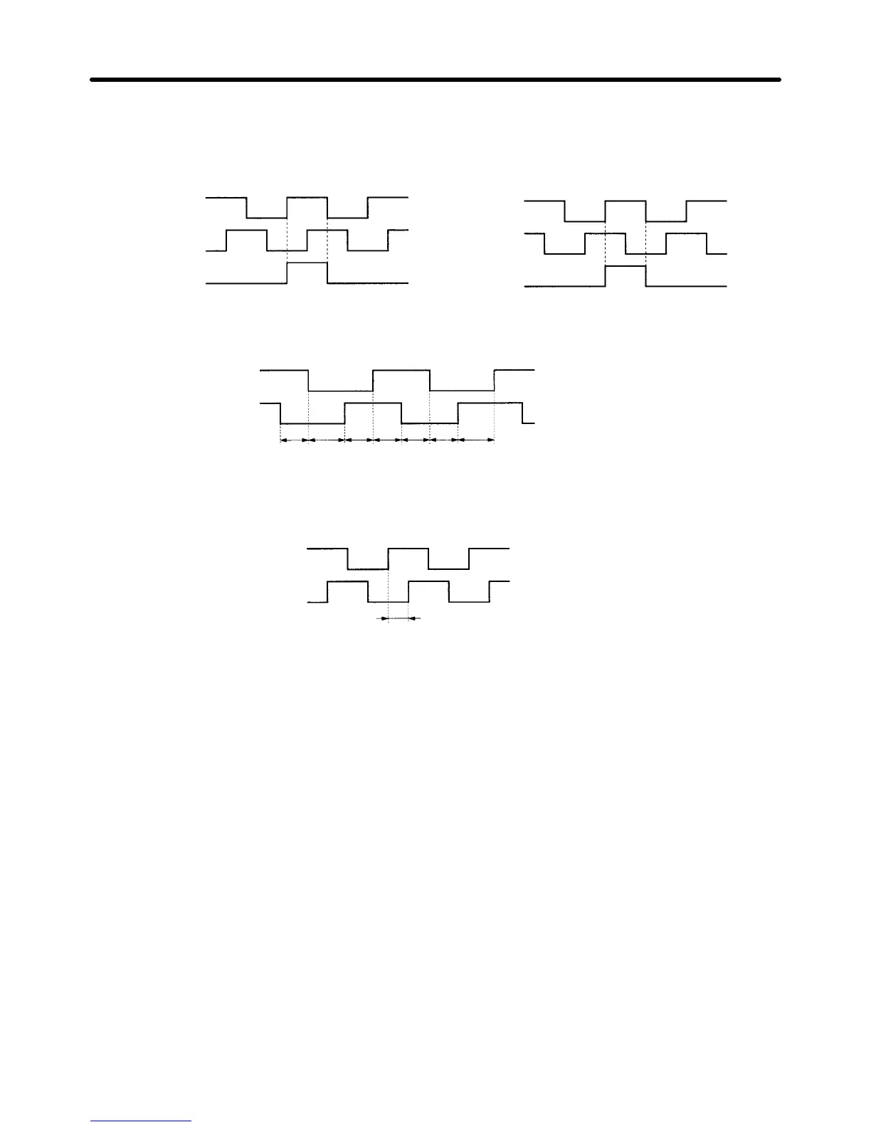
• The output phases of the encoder signal output from the Servo Driver are as shown below (when divid-
er ratio Pn201 = encoder resolution).
Forward rotation side Reverse rotation side
Phase A
Phase B
Phase Z
Phase A
Phase B
Phase Z
• When the encoder divider rate is set to other than 2
n
(16,384, 8,192, 4,096, 2,048, 1,024, etc.), the
phase difference for phases A and B is not 90°, but scatters for time T. (See the diagram below.)
t1
t2
t1
Phase A
Phase B
t1 t1 t1
t2
t1 = nT, t2 = (n+1)T
In this diagram, T represents the processing circuit output between phase A and phase B, and n is an
integer that satisfies the following formula (with digits below the decimal point discarded).
n = resolution/encoder divider rate
Phase A
Phase B
Input to frequency divider
(processing circuit output)
T
4-5-8 Brake Interlock (All Operating Modes)
H Precautions for Using Electromagnetic Brake
• The electromagnetic brake Servomotor with a brake is a non-excitation brake especially for holding.
First stop the Servomotor, then turn OFF the power supply to the brake before setting the parameters.
If the brake is applied while the Servomotor is operating, the brake disk may become damaged or mal-
function due to friction, causing damage to the Servomotor.
H Function
• You can set the BKIR (brake interlock) signal output timing to turn ON and OFF the electromagnetic
brake.
Operation Chapter 4
 Loading...
