5-9
5-3 Troubleshooting
If an error occurs in the machinery, check the type of error using the alarm indicators and
operation status, verify the cause, and take appropriate countermeasures.
5-3-1 Error Diagnosis Using Alarm Display
Note 1. If an Option Unit is installed, an Option Unit error code may be output. For details, also refer to
the operation manual for the Option Unit.
Note 2. Alarms marked with one asterisk are supported for Servo Drivers with a software version of
“r.0014” or later.
Note 3. Warnings marked with two asterisks are supported for Servo Drivers with a software version
of “r.0037” or later.
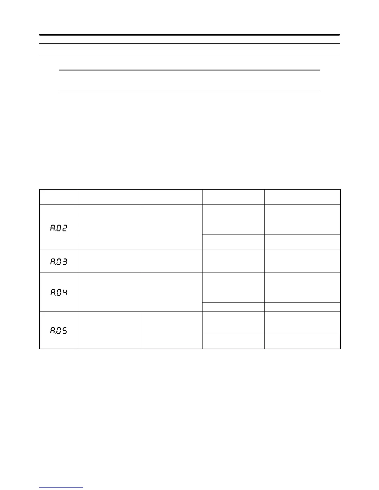
Display Error Status when error
occurs
Cause of error Countermeasures
Parameters cor-
rupted
Occurs when control
circuit power supply
is turned ON.
Power supply was
turned OFF while
parameters were
being written.
Initialize (Fn005) the user
parameters, and then re-
set the parameters.
Internal memory er-
ror
Replace the Servo Driver.
Main circuit detec-
tion error
Occurs when main
circuit power supply
is turned ON.
Main circuit detec-
tion data error
Replace the Servo Driver.
Parameter setting
error
Occurs when control
circuit power supply
is turned ON.
A value outside of
the setting range
was previously set in
the parameters.
Reset the parameters
within the setting range.
Control panel error Replace the Servo Driver.
Servomotor mis-
match
Occurs when control
circuit power supply
is turned ON.
Servomotor and
Servo Driver com-
bination is incorrect.
Correct the combination.
Encoder internal
data error
Replace the Servomotor.
Troubleshooting Chapter 5
 Loading...
