4-7
D Operation Procedure
PR02W
operation
Front panel
key operation
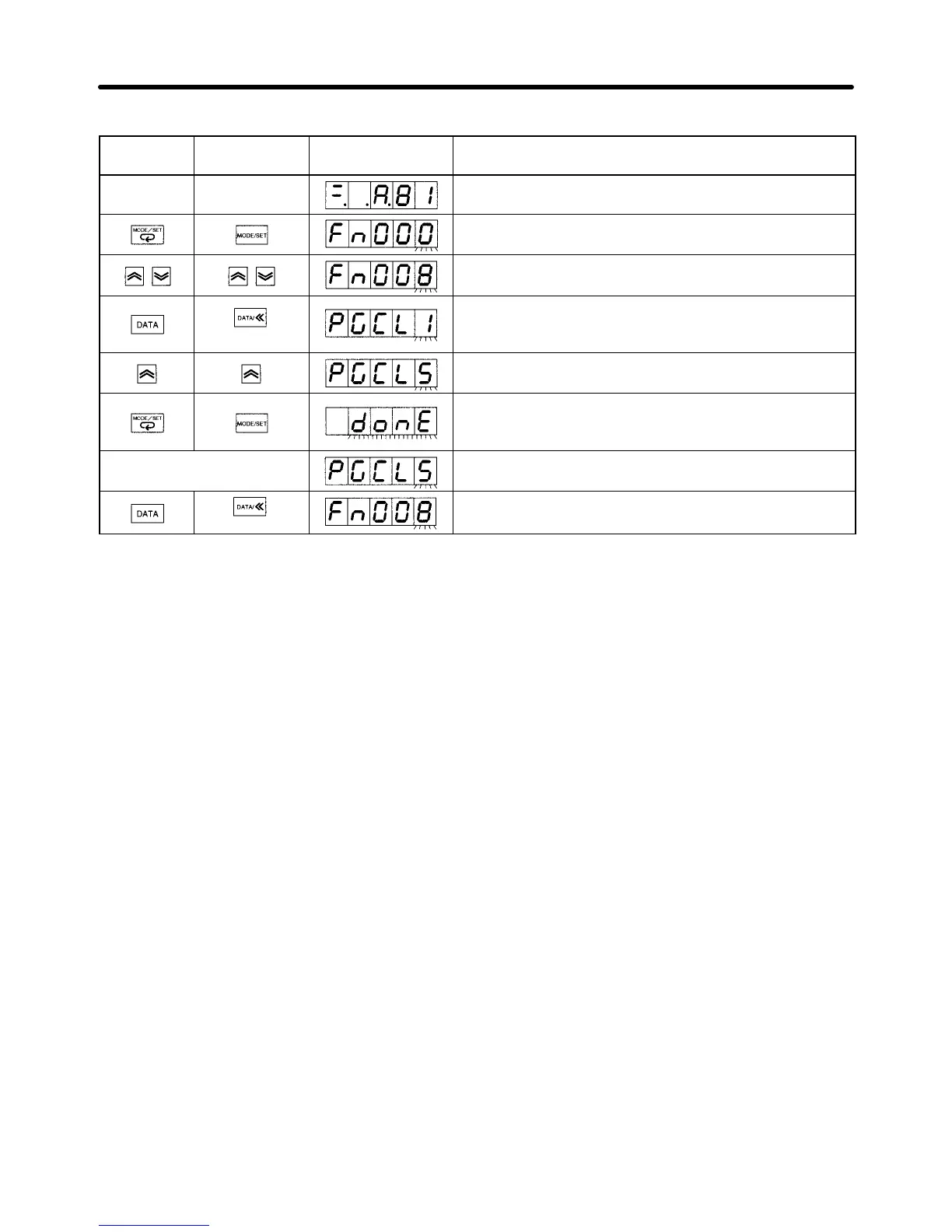
Display example Explanation
Status Display Mode. (See note.)
Press the MODE/SET Key to change to System Check
Mode.
Press the Up or Down Key to select function Fn008.
(1 s min.)
Press the DATA Key (front panel: DATA Key for 1 s min.)
to enter the absolute encoder setup functions. PGCL1
will be displayed.
Press the Up Key to display PGCL5.
Press the MODE/SET Key to set up the absolute
encoder. When setup is complete, “donE” will flash for
approximately 1 s.
(Approx. 1 s later) After “donE” has been displayed, the display will return
to “PGCL5.”
(1 s min.)
Press the DATA Key (front panel: DATA Key for 1 s min.)
to display the System Check Mode function code.
Note When connecting a Servomotor with an absolute encoder and turning ON the power for the first
time, A.81 (backup error) will be displayed.
D Turn ON the Power
The alarm (A.81) will not be cancelled with the setup operation. Turn OFF the power (and check that
the power indicator is not lit), then turn ON the power again to cancel the alarm. After the power is
turned ON again, as long as there is no error, the setup procedure is complete at this point. If an alarm
(A.81) occurs, repeat the previous step.
H Additional Setup Operations
D Trial Operation Setup
• The preceding setup is necessary to check the Servomotor and Servo Driver operations (without a
load). When connecting the Servomotor and mechanical system for a trial operation, the absolute
encoder may rotate excessively. If that occurs, perform the setup once again.
• When connecting to the CV500-MC221/421 or C200H-MC221 Motion Control Unit, carry out the set-
up close to the mechanical origin. An error will be generated if the absolute data exceeds ±32,767
pulses when making the initial settings for the CV500-MC221/MC421 or C200H-MC221 Motion
Control Unit (This limitation does not apply to the CS1W-MC221/MC241 Motion Control Unit).
Note The number of rotations and the output range for the OMNUC W-series absolute encoders are
different from the previous models (U series).
W series: Number of rotations and output range: –32,768 to 32,767
U series: Number of rotations and output range: –99,999 to 99,999
Set the operating range within the number of rotations and output range.
Operation Chapter 4

 Loading...