4-133
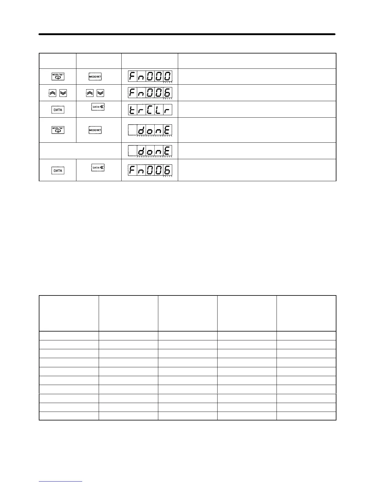
Operation Procedure
PR02W
operation
Front panel
key operation
Display Explanation
Press the MODE/SET Key to change to System Check
Mode.
Press the Up or Down Key to set function code Fn006.
(See note.)
(1 s min.)
Press DATA Key (front panel: DATA Key for 1 s min.) to
display “trCLr.”
Press the MODE/SET Key to clear the alarm history
data. When the data has been cleared, “donE” will flash
for approximately 1 s.
(Approx. 1 s later) After “donE” has been displayed, the display will return
to “trCLr.”
(1 s min.)
Press the DATA Key (front panel: DATA Key for 1 s
min.). The display will return to the System Check Mode
function code.
Note The digits you can manipulate will flash.
4-11-2 Online Auto-tuning Functions
• In System Check Mode, online auto-tuning consists of the rigidity setting (Fn001) and saving tuning
results (Fn007).
H Rigidity Setting During Online Auto-tuning (Fn001)
• The rigidity setting during online auto-tuning sets the target speed loop gain and position loop gain for
the servo system.
• Select the rigidity setting according to the following 10 levels for the mechanical system.
Rigidity setting
Fn001
(d.00jj)
Position loop gain
[s
–1
]
Pn102
Speed loop gain
[Hz]
Pn100
Speed loop
integration time
constant
[x 0.01 ms]
Pn101
Torque command
filter time
constant
[x 0.01 ms]
Pn401
01 15 15 6000 250
02 20 20 4500 200
03 30 30 3000 130
04 40 40 2000 100
05 60 60 1500 70
06 85 85 1000 50
07 120 120 800 30
08 160 160 600 20
09 200 200 500 15
10 250 250 400 10
Note 1. The higher the rigidity setting, the higher the servo system loop gain, and the shorter the posi-
tioning time. If the set value is too high, however, the machinery may vibrate. If vibration oc-
curs, lower the setting.
Operation Chapter 4

 Loading...