2-68
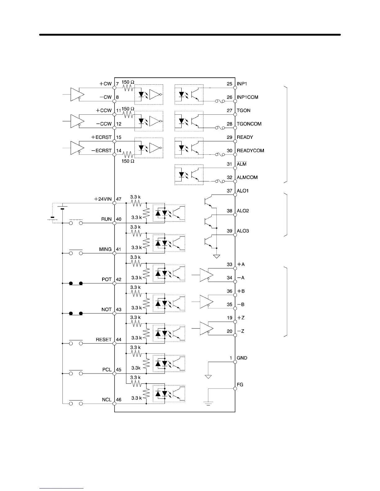
2-4-4 Control I/O Specifications (CN1)
H Control I/O and External Signals for Position Control
Reverse
pulse
Forward
pulse
Deviation
counter
reset
24 V DC
RUN command
Gain
deceleration
Forward rotation
drive prohibit
Alarm reset
Forward rotation
current limit
Reverse rotation
current limit
Reverse rotation
drive prohibit
Line driver output
EIA-RS422A
conforming
(Load resistance:
220 Ω min.)
Maximum oper-
ating voltage:
30 V DC
Maximum out-
put current:
50 mA
Maximum oper-
ating voltage:
30 V DC
Maximum out-
put current:
20 mA
Ground common
Positioning
completed
output 1
Servo ready
Alarm output
Alarm code
outputs
Encoder A
phase outputs
Frame ground
Encoder B
phase outputs
Encoder Z
phase outputs
Shell
Motor rotation
detection
(See note 2.)
(See note 2.)
(See note 2.)
(See note 2.)
Note 1. The inputs at pins 40 to 46 and the outputs at pins 25 to 30 can be changed by parameter settings. The
settings in the diagram are the defaults.
Note 2. An automatic reset fuse is provided to protect output. If the fuse is activated for overcurrent, it will auto-
matically reset after a fixed period of time has lapsed without current flowing (supported by Servo Driv-
ers with software version “r.0037” or later).
Standard Models and Specifications Chapter 2

 Loading...