4-81
mand inputs can be received in this status. The pulse command is input after INP1 is turned
ON. Until INP1 is turned ON, pulse inputs are ignored.
Note 2. After INP1 has turned ON, turn ON the speed selection command in the same way as when
switching from position control to internally-set speed control.
Note 3. There is a maximum delay of 2 ms in reading the input signal.
Note 4. The shaded areas in the time chart for the positioning completed signal (INP1) indicate the
places where the signal is turned ON as the VCMP (speed compare) signal. (The meaning of
the signal differs according to the control mode.)
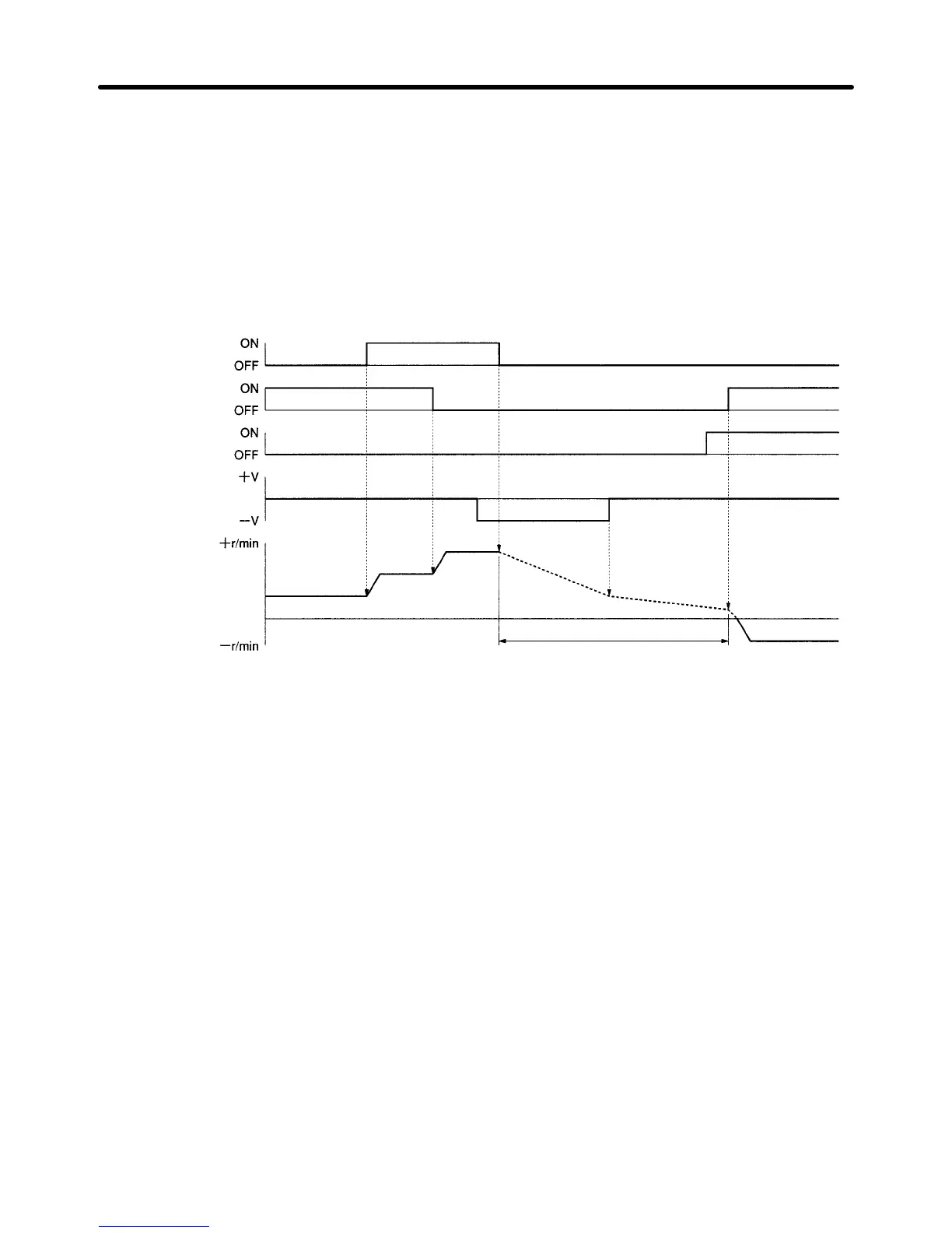
D Internally-set Speed Control + Torque Control (Pn000.1 = 6)
Speed selection
command 1
SPD1
Speed selection
command 2
SPD2
Rotation direction
command
RDIR
Torque command
input
TREF
Servomotor op-
eration
Speed 2
Speed 3
Speed 1
Speed 1 (reverse
rotation)
Torque Control Mode
Note 1. Operation follows the speed command input (TREF) immediately after SPD1 and SPD2 are
both OFF (although there is a delay of up to 2 ms in reading the input signal).
Note 2. Servomotor operation with torque control varies according to the Servomotor load conditions
(e.g., friction, external power, inertia). Perform safety measures on the devices to prevent
Servomotor runaway.
Note 3. When Servomotor servo-lock is required, set any of the internal speed settings to 0 r/min and
select that speed with SPD1 and SPD2 (speed selection commands 1 and 2).
Operation Chapter 4

 Loading...