4-18
4-2 Wiring
4
System Design
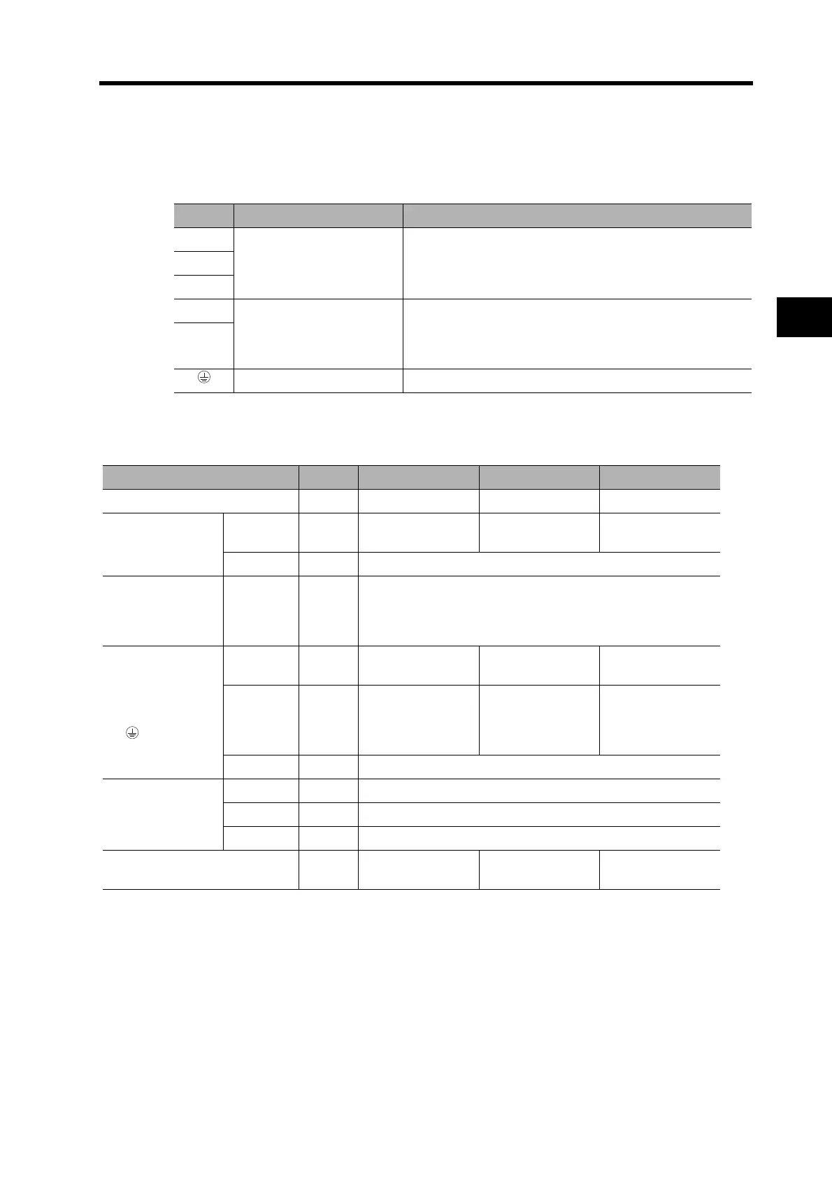
Main Circuit Wiring
When wiring a Terminal Block, use proper wire sizes, grounding systems, and take into account
anti-noise characteristics.
Terminal Names and Functions
Terminal Wire Sizes
Signal Name Function
L1
Main circuit power supply
input
Single-phase 100 to 115 VAC (85 to 126 VAC), 50/60 Hz
Single-phase/three-phase 200 to 230 VAC (170 to 264 VAC),
50/60 Hz
L2
L3
P
External regeneration
resistor connection
terminals
Do not short-circuit P and B1. Doing so may result in malfunc-
tions.
If regenerative energy is high, connect an External Regener-
ation Resistor.
B1
Frame ground This is the ground terminal. Ground to 100 Ω or less.
Item Unit R7D-BPA5L R7D-BP01L R7D-BP02L
Power supply capacity kVA 0.16 0.25 0.42
Main circuit power
supply input (L1,
L2)
Rated
current
A(rms) 1.4 2.2 3.7
Wire size AWG18
External
Regeneration
Resistor
connection (+, −)
Wire size AWG18
Servomotor
connection
terminal (U, V,
W, )
*1
*1. Connect an OMRON Servomotor Power Cable to the Servomotor connection terminals.
Rated
current
A(rms) 1.0 1.6 2.5
Maximum
momen-
tary
current
A(rms) 3.3 5.1 7.5
Wire size AWG18
Frame ground
Wire size AWG14 min.
Screw size --- M4
Torque N·m 1.2 to 1.4
No-fuse breaker or fuse
capacity
*2
*2. Use a no fuse breaker or a surge withstand fuse. The maximum inrush current is 20 A.
A(rms) 3 5 7

 Loading...