85
I/O Memory Allocations Section 2-3
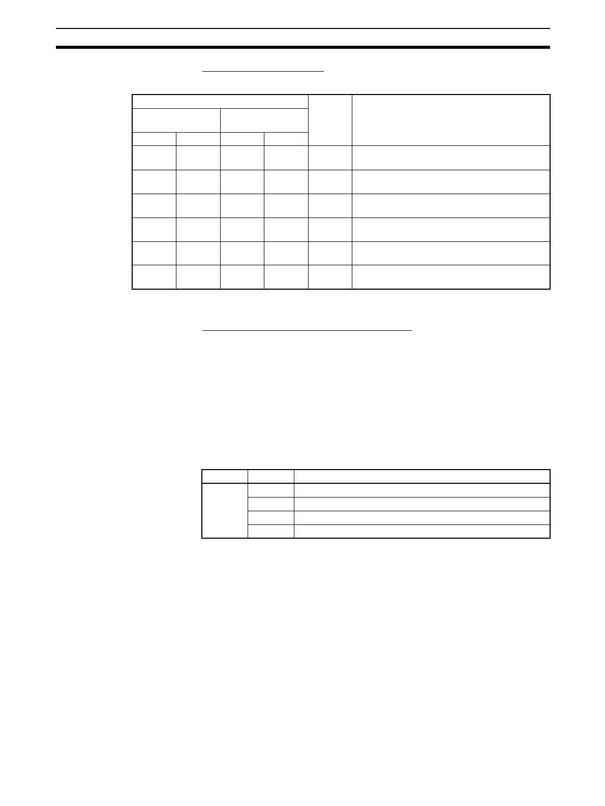
Modbus-RTU Slave Mode
n = CIO 1500 + 25 × unit number
2-3-3 Related Auxiliary Area Bits
Serial Communications
Boards (CS Series Only)
Port 1 and Port 2 Port Settings Change Bits
These bits can be turned ON from the program using the OUT or other
instructions to change communications settings and restart the Serial Com-
munications Board ports. When changing the settings and restarting the port
have been completed, the bit will automatically be turned OFF.
Note These bits are used both to change the port settings and to restart the port at
the same time. One of these bits can be turned ON to restart a port without
changing the port settings in the Setup Area allocated in the DM Area. The
STUP(237) instruction can also be used to just restart a communications port
by executing STUP(237) with the same port settings as the ones already
being used.
Words Bit Contents
Board
(CS Series only)
Unit
(CS/CJ Series)
Port 1Port 2Port 1Port 2
CIO
1909
CIO
1919
n + 09 n + 19 15 to 00 Number of normally received commands
CIO
1910
CIO
1920
n + 10 n + 20 15 to 00 Number of normally sent responses
CIO
1911
CIO
1921
n + 11 n + 21 15 to 00 Number of overrun errors, framing errors, and
parity errors (transmission errors)
CIO
1912
CIO
1922
n + 12 n + 22 15 to 00 Number of CRC errors (transmission errors)
CIO
1913
CIO
1923
n + 13 n + 23 15 to 00 Number of command format errors (illegal func-
tion codes and illegal addresses)
CIO
1914
CIO
1924
n + 14 n + 24 15 to 00 Reserved.
Word Bit Contents
A636 03 to 15 Reserved
02 1: Port 2 Settings Change Bit
01 1: Port 1 Settings Change Bit
00 Reserved
 Loading...


