95
Wiring Section 3-3
3-3 Wiring
3-3-1 Wiring Precautions
• Before connecting or disconnecting the communications cables, always
make sure that the PLC is turned OFF.
• Tighten the communications connector screws firmly with your fingers.
• Serial Communications Boards and Units can be connected to various
devices. For compatibility, refer to the operation manuals for the devices
to which they are to be connected.
3-3-2 Port Types
The following port types are provided on the Serial Communications Boards
and Units.
The following sections describe the connection methods used for each serial
communications mode of the Serial Communications Board and Unit ports.
3-3-3 Communications Modes and Ports
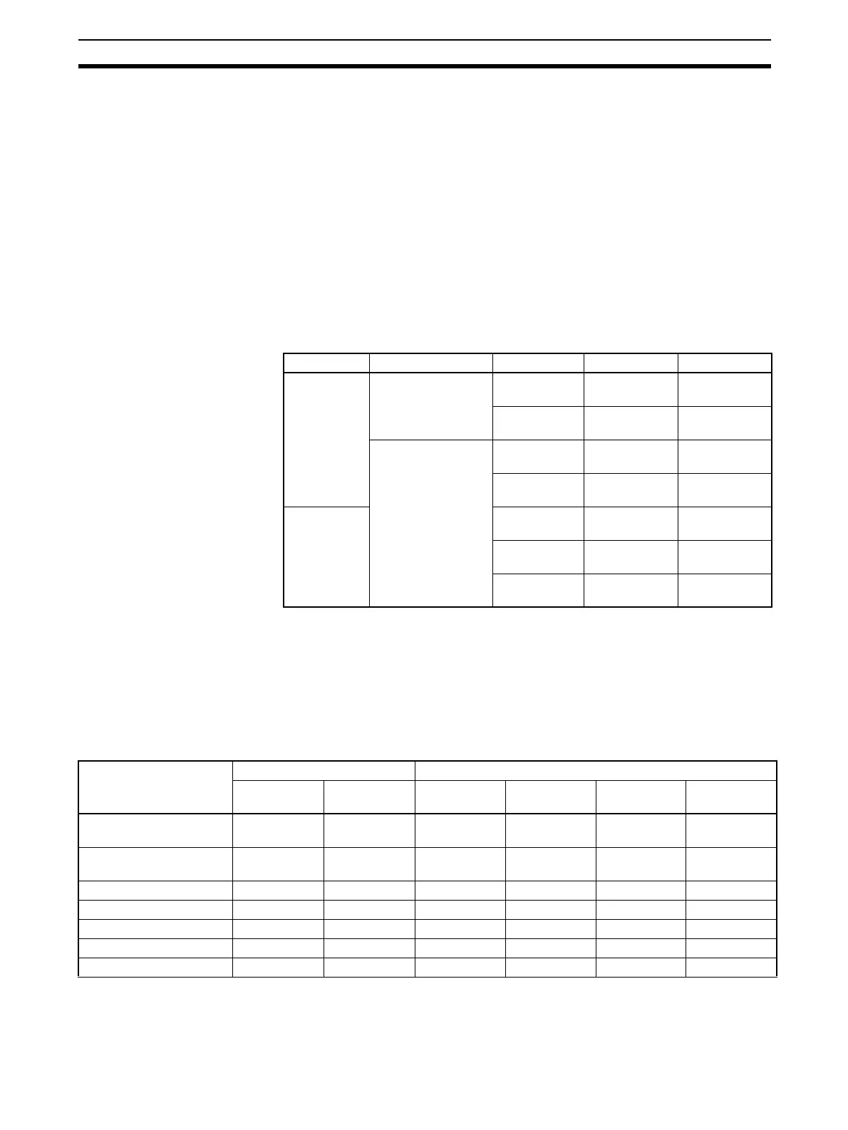
The following table shows the relationship between the communications ports
and the communications modes for the Serial Communications Boards and
Unit. Serial Communications Units provide only RS-232C ports.
Note 1. The NT-AL001-E Link Adapter can be used to convert between RS-232C
and RS-422A/485 to enable 1:N communications.
2. Use 4-wire connections between Link Adapters.
PLC Series Unit type Model Port 1 Port 2
CS Series Serial Communica-
tions Board
CS1W-
SCB21-V1
RS-232C RS-232C
CS1W-
SCB41-V1
RS-232C RS-422A/485
Serial Communica-
tions Unit
CS1W-
SCU21-V1
RS-232C RS-232C
CS1W-
SCU31-V1
RS-422A/485 RS-422A/485
CJ Series CJ1W-
SCU21-V1
RS-232C RS-232C
CJ1W-
SCU31-V1
RS-422A/485 RS-422A/485
CJ1W-
SCU41-V1
RS-422A/485 RS-232C
Communications mode RS-232C RS-422A/485
1:1 1:N
(see note 1)
1:1 4-wire 1:N 4-wire 1:1 2-wire 1:N 2-wire
Host Link YES YES
(see note 2)
YES YES No No
1:1 Host Link YES YES
(see note 2)
YES No No No
Protocol macros YES YES YES YES YES YES
Serial Gateway YES YES YES YES YES YES
No-protocol YES YES YES YES No No
NT Link YES YES YES YES YES YES
Modbus-RTU slave YES YES YES YES YES YES
 Loading...


