623
V500/V520 Bar Code Reader Protocol Appendix M
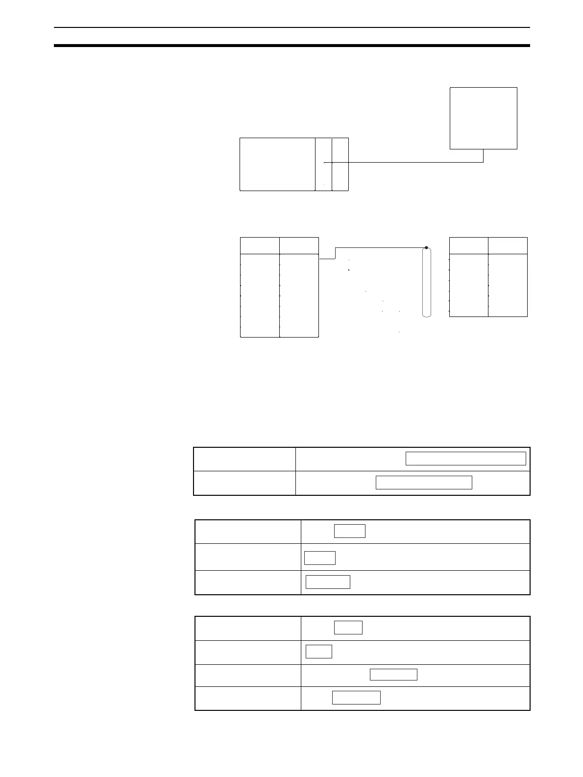
V520 Connections
System Setting
Shown below are the system settings of the V500-C11 and V520-R121 when this protocol is used.
Note The portions enclosed by in boxes are used for this protocol.
V500-C11
• BCR Functions
• Host Interface
V520-R121
Read trigger
Read control method
Prefix
Suffix
Bar code output
Start code
Stop code
Operation mode
Data output mode
RS-232C port
Reader
Signal
Name
Signal
Name
Pin No.
Pin No.
V509-W011
Reader Cable
V520-R121
Serial Communications Unit/Board:
D-sub 9 pin female
V520-R121:
D-sub 9 pin female
FG
SD
RD
RTS
CTS
DSR
DTR
SG
SD
RD
RTS
CTS
DTR
SG
Serial Communications Board
(CS Series only)
Serial Communications Unit
(CS/CJ Series)
1
2
3
4
5
7
8
9
1
2
3
4
6
7
PLC PS
"READ SIGNAL INPUT", "ONLINE READ COMMAND"
"SINGLE READ", "CONTINUOUS READ"
NONE, "STX"
"ETX" , "CR "
"OUTPUT" , "NO OUTPUT"
NONE, "STX"
"ETX" , "CR"
External trigger, host trigger
1-shot, continuous
 Loading...


