117
RS-232C and RS-422A/485 Wiring Section 3-4
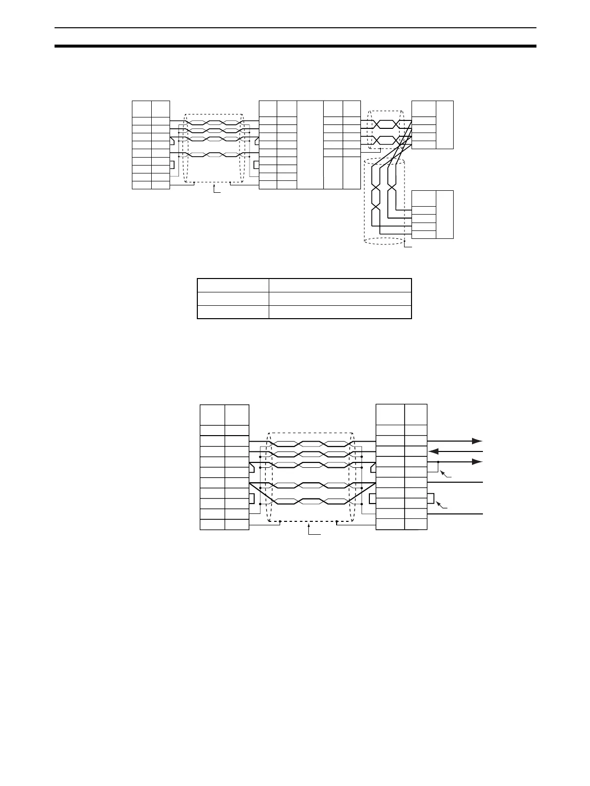
• With NT-AL001-E RS-232C/RS-422 Link Adapter
Note 1. The following cables are available for this connection.
It is recommended that one of these cables be used to connect the RS-
232C port on the Serial Communications Board or Unit to the NT-AL001-E
RS-232C/RS-422 Link Adapter. The recommended wiring for these cables
is shown below.
2. The XW2Z-070T-1 and XW2Z-200T-1 Connecting Cables for the NT-
AL001-E Link Adapter uses special wiring for the DTS and RTS signals.
Do not use these signals with other devices; they may be damaged.
3. The Hood (FG) is internally connected to the ground terminal (GR) on the
Power Supply Unit via the CPU Rack or Expansion Rack. Therefore, FG is
grounded by grounding the ground terminal (GR) on the Power Supply
Unit.
RS-422
FG
RS-232C
Serial Communications
Board/Unit
Pin
Remote device
Remote device
NT-AL001-E
Signal
Pin
Signal Signal
Pin
Signal
Signal
Shield
(See note.)
Hood
SD
RD
RS
CS
5V
DR
ER
SG
FG
RD
SD
RS
CS
5V
DR
ER
SG
2
3
4
5
6
7
8
9
3
4
5
6
7
8
9
2
4
3
6
5
1
FG
SDA
SDB
RDA
RDB
GRD
SDA
SDB
RDA
RDB
SDA
SDB
RDA
RDB
Hood
Length Model
70 cm XW2Z-070T-1
2 m XW2Z-200T-1
Pin
Signal
Shield
Hood
SD
RD
RS
CS
5V
DR
ER
SG
FG
2
3
4
5
6
7
8
9
FG1
Signal
Pin
1
3
Hood
2
4
5
6
7
8
9
RD
SD
RS
CS
5V
DR
ER
SG
FG
SYSMAC PLC
NT-AL001-E
(internal)
Arrows indicate
signal directions
Loopback
Loopback
Not used.
 Loading...


