14-49
14 Serial Communications
CP2E CPU Unit Software User’s Manual(W614)
14-7 Modbus-RTU Slave Function
14
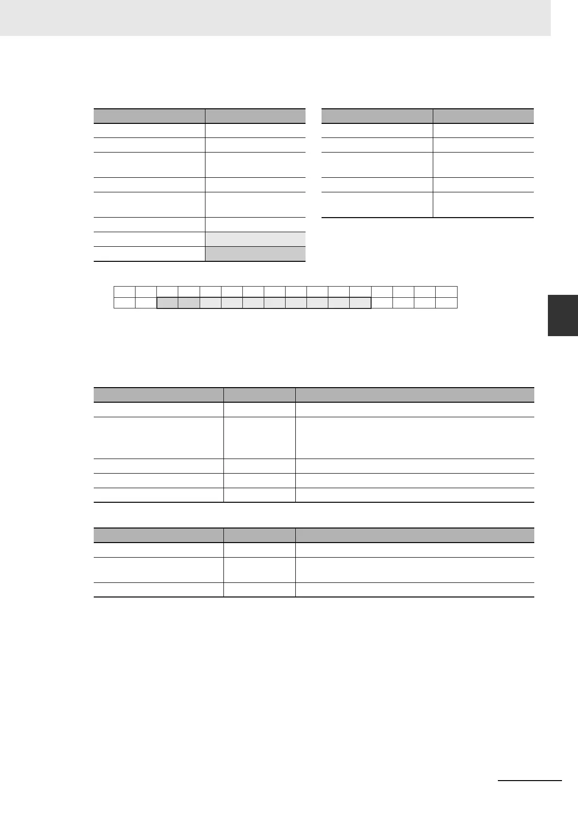
14-7-5 Command and Response Details
Example: Writing 10 bits (xxxx xx11 1100 1101) from W1.04 to W1.13
Command (Modbus-RTU Master) Response (CP2E)
Note The subscript numbers in the shaded boxes indicate the ON/OFF (1/0) status of the bits that are written.
Other bits in the same word are set to 0.
z Write Multiple Words in the Data Memory (D) (Write Multiple Registers)
Command (Modbus-RTU Master)
Response (CP2E)
Field name Data Field name Data
Function code 06 Hex Function code 0F Hex
Starting address (H) 00 Hex Starting address (H) 00 Hex
Starting address (L) 14 Hex
(W1.04~)
Starting address (L) 14 Hex
Quantity of output (H) 00 Hex Quantity of output (H) 00 Hex
Quantity of output (L) 0A Hex
(10 bits)
Quantity of output (L) 0A Hex
Byte count 02 Hex
Output value(H)
3A Hex
Output value(L)
01 Hex
Field name Data length Data
Function code 1 byte 10 Hex
Starting address 2 bytes E-type: 0 to 0FFF Hex (D0 to D4095)
S-type: 0 to 1FFF Hex (D0 to D8191)
N-type: 0 to 3FFF Hex (D0 to D16383)
Quantity of registers 2 bytes 0001 to 07B Hex (1 to 123)
Byte count 1 byte 2×N (N: Quantity of registers)
Registers value 2×N bytes
Field name Data length Data
Function code 1 byte 10 Hex
Starting address 2 bytes 0 to 7FF Hex (0 to 2047)
W0.00 to W127.15
Quantity of registers 2 bytes 0001~07BHex (1~123)
15
14 13 12 11 10 9 8 7 6 5 4 3 2 1 0
15
14 13 12 11 10 9 8 7 6 5 4 3 2 1 0
31
30 29 28 27 26 25 24 23 22 21 20 19 18 17 16
0
00 10 0 11 101 00 000
0CH
1CH
 Loading...


