EasyManua.ls Logo

Omron SYSMAC CS/CJ Series User Manual

Omron SYSMAC CS/CJ Series
383 pages
To Next Page IconTo Next Page
To Previous Page IconTo Previous Page
Page #271 background imageLoading...
Page #271 background image
250
Cycle Time/High-speed Processing Section 6-1
Programming Example 2
This examples show background execution when index register output is
specified, as is possible for MAX(182), MIN(183), and SRCH(181).
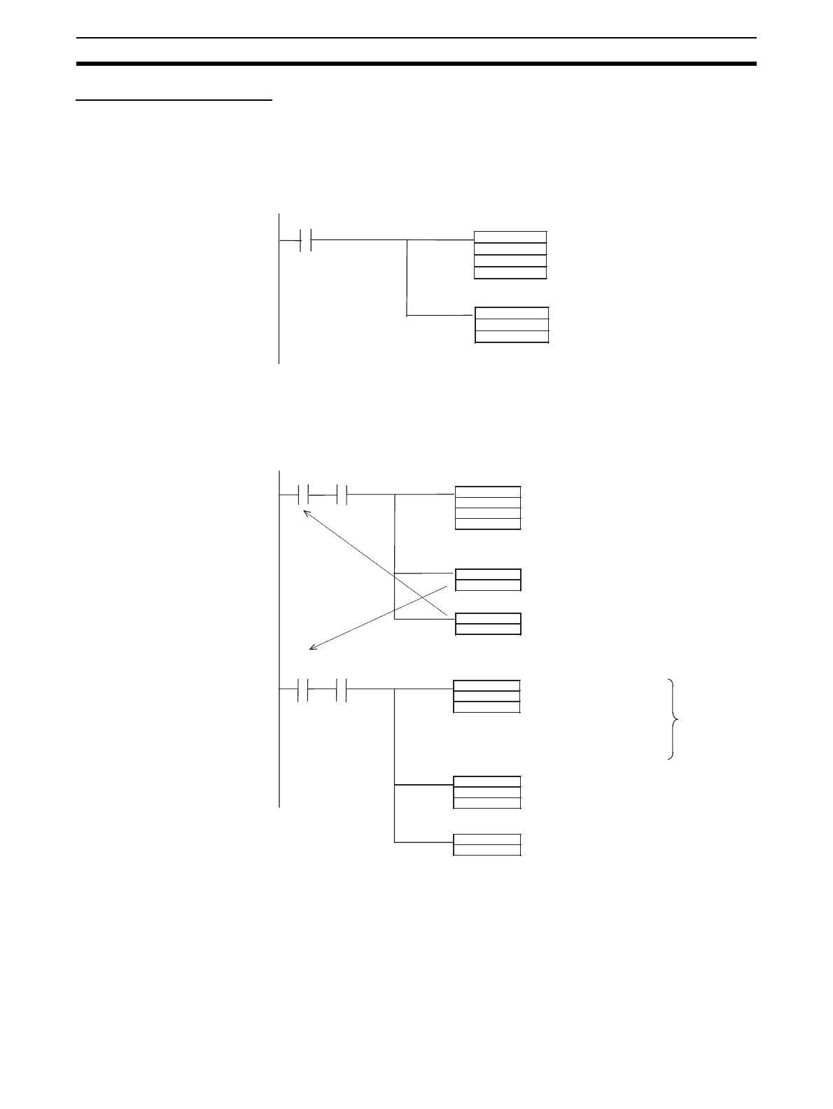
Traditional Programming without Background Execution
As shown below, the actual memory map address of the word containing the
maximum value is output to an index register.
Programming with Background Execution
With background execution, the actual memory map address of the word con-
taining the maximum value is output to A595 and A596. MOVL(498) is then
used the actual memory map address to the index register.
6-1-11 Sharing Index and Data Registers between Tasks
Sharing Index and Data Registers (IR/DR) between tasks is supported only by
CS1-H, CJ1-H, or CJ1M CPU Units. The normal setting is for separate regis-
ters for each task. The current setting can be confirmed in A09914.
Note 1. Shared Index and Data Registers can be used to eliminate the need to
store and load register contents between tasks when the same contents is
needed in two or more tasks. Refer to the section on index registers in the
MAX
D00000
D00100
D00200
a
MOV
,IR0
D00300
Execution condition
MAX(182) is executed completely as
soon as the execution condition “a”
turns ON, and the actual memory map
address of the word containing the
maximum value is output to IR0
The contents of the I/O memory word
indicated by the memory map
address in IR0 is copied to D00300.
RSET
a
SET
b
MAX
D00000
D00100
D00200
a A20200
MOV
,IR0
D00300
MOVL
A595
IR0
b A20200
RSET
b
Execution condition “b” is turned ON to
execute MOVL(498).
When execution condition “b”
is ON and the
Communications Port
Enabled Flag is ON,
MOVL(498) copies the actual
memory map address in
A595 and A596 to IR0.
MAX(182) execution is started if execution
condition “a” is ON and the Communications
Port Enabled Flag is ON. The actual memory
map address of the word containing the
maximum value is output to A595 and A596.
“a” is turned OFF so that MAX(182) will not
be executed the next cycle.
The contents of the I/O memory word
indicated by the memory map address in IR0
is copied to D00300.
Extra
processing
required to
move
address.
Execution
condition
Communications
Port Enabled Flag
Execution
condition
Communications
Port Enabled Flag

Table of Contents

Question and Answer IconNeed help?

Do you have a question about the Omron SYSMAC CS/CJ Series and is the answer not in the manual?

Omron SYSMAC CS/CJ Series Specifications

General IconGeneral
SeriesCS/CJ Series
CategoryController
Programming LanguagesLadder Diagram, Structured Text, Function Block Diagram, Sequential Function Chart
I/O CapacityVaries by model (e.g., up to 5120 I/O points)
Communication PortsRS-232C, RS-422/485
MountingDIN rail
Power SupplyAC or DC (varies by model)
CPU TypeVarious CPUs available within the CS/CJ series (e.g., CS1H, CS1G, CS1D, CJ1M, CJ2M, CJ2H)
Ethernet SupportYes (varies by model)
Operating Temperature0°C to 55°C (32°F to 131°F)

Summary

PRECAUTIONS

1 Intended Audience

Specifies the intended audience for this manual, requiring electrical system knowledge.

2 General Precautions

General guidelines for operating OMRON products according to specifications and consulting representatives.

3 Safety Precautions

Critical safety warnings regarding PLC usage, I/O memory, and handling units.

4 Operating Environment Precautions

Precautions for operating the PLC system in various environmental conditions.

5 Application Precautions

Precautions to observe when using the PLC system, including software and data transfer.

6 Conformance to EC Directives

Information on compliance with EMC and Low Voltage directives for CS/CJ PLCs.

SECTION 1: CPU Unit Operation

1-1 Initial Setup (CS1 CPU Units Only)

Procedures for initial setup and battery installation for CS1 CPU Units.

1-2 Using the Internal Clock (CS1 CPU Units Only)

How to set and use the internal clock for CS1 CPU Units.

1-3 Internal Structure of the CPU Unit

Overview of CPU Unit internal structure, memory, and diagrams.

1-4 Operating Modes

Description of PROGRAM, MONITOR, and RUN modes of the CPU Unit.

1-5 Programs and Tasks

Explains how programs are grouped into tasks for execution.

1-6 Description of Tasks

Details various types of tasks like cyclic and interrupt tasks.

SECTION 2: Programming

2-1 Basic Concepts

Fundamental concepts for writing CS/CJ-series PLC programs.

2-2 Precautions

Important precautions when programming, focusing on flags and sections.

2-3 Checking Programs

Procedures for checking programs for errors using CX-Programmer or console.

SECTION 3: Instruction Functions

3-1 Sequence Input Instructions

Instructions for handling input signals and execution conditions.

3-2 Sequence Output Instructions

Instructions for outputting results of logical processing to bits.

3-3 Sequence Control Instructions

Instructions for controlling program flow, such as END, JMP, and IL.

3-4 Timer and Counter Instructions

Details on various timer and counter instructions.

3-5 Comparison Instructions

Instructions for comparing values and creating execution conditions.

3-6 Data Movement Instructions

Instructions for transferring data between memory areas.

3-7 Data Shift Instructions

Instructions for shifting bits or words within data.

3-8 Increment/Decrement Instructions

Instructions for incrementing or decrementing numerical data.

3-9 Symbol Math Instructions

Instructions for performing arithmetic operations on signed binary and BCD data.

3-10 Conversion Instructions

Instructions for converting data between BCD, binary, and ASCII formats.

3-11 Logic Instructions

Instructions for performing logical operations (AND, OR, XOR) on bits and words.

3-12 Special Math Instructions

Instructions for specialized mathematical operations like square roots.

3-13 Floating-point Math Instructions

Instructions for performing mathematical operations on floating-point numbers.

3-14 Double-precision Floating-point Instructions (CS1-H, CJ1-H, or CJ1M Only)

Instructions for handling double-precision floating-point data.

3-15 Table Data Processing Instructions

Instructions for manipulating data in tables and stacks.

3-16 Data Control Instructions

Instructions for controlling data flow and scaling.

3-17 Subroutine Instructions

Instructions for calling and managing subroutines and macros.

3-18 Interrupt Control Instructions

Instructions for setting up and managing interrupt tasks.

3-19 High-speed Counter and Pulse Output Instructions (CJ1M-CPU22/23 Only)

Instructions for high-speed counter and pulse output.

3-20 Step Instructions

Instructions for step-by-step program execution.

3-21 Basic I/O Unit Instructions

Instructions for interacting with basic I/O units.

3-22 Serial Communications Instructions

Instructions for serial communications.

3-23 Network Instructions

Instructions for network communication.

3-24 File Memory Instructions

Instructions for manipulating file memory.

3-25 Display Instructions

Instructions for displaying messages.

3-26 Clock Instructions

Instructions for calendar and time operations.

3-27 Debugging Instructions

Instructions and functions for debugging programs.

3-28 Failure Diagnosis Instructions

Instructions for diagnosing and reporting failures.

3-29 Other Instructions

Miscellaneous instructions not covered elsewhere.

3-30 Block Programming Instructions

Instructions for creating and managing block programs.

3-31 Text String Processing Instructions

Instructions for processing text strings.

3-32 Task Control Instructions

Instructions for controlling task execution status.

SECTION 4: Tasks

4-1 Task Features

Overview of tasks, their advantages, and structure.

4-2 Using Tasks

How to use TASK ON/OFF instructions and manage task status.

4-3 Interrupt Tasks

Details on types, priority, flags, and precautions for interrupt tasks.

4-4 Programming Device Operations for Tasks

How to manage tasks using CX-Programmer and Programming Console.

SECTION 5: File Memory Functions

5-1 File Memory

Information on types of file memory, data, files, and procedures.

5-2 Manipulating Files

Procedures for reading, writing, and managing files using various methods.

5-3 Using File Memory

Procedures for initializing Memory Cards and EM File Memory.

SECTION 6: Advanced Functions

6-1 Cycle Time/High-speed Processing

Functions related to cycle time optimization and high-speed operations.

6-2 Index Registers

Explanation of index registers and their usage for indirect addressing.

6-3 Serial Communications

Details on serial communication protocols like Host Link and No-protocol.

6-4 Changing the Timer/Counter PV Refresh Mode

How to select and configure BCD or binary modes for timer/counter PVs.

6-5 Using a Scheduled Interrupt as a High-precision Timer (CJ1M Only)

Using scheduled interrupts as high-precision timers.

6-6 Startup Settings and Maintenance

Functions related to system startup, maintenance, and protection.

6-7 Diagnostic Functions

Overview of diagnostic tools like error logs and failure diagnosis.

6-8 CPU Processing Modes

Details on normal and parallel processing modes.

6-9 Peripheral Servicing Priority Mode

Settings for prioritizing peripheral servicing.

6-10 Battery-free Operation

Procedures for operating without a battery using flash memory or Memory Cards.

6-11 Other Functions

Includes I/O response time settings and I/O area allocation.

SECTION 7: Program Transfer, Trial Operation, and Debugging

7-1 Program Transfer

Procedures for transferring programs to the CPU Unit.

7-2 Trial Operation and Debugging

Functions for testing and debugging programs, including forced set/reset and tracing.

Appendix A: PLC Comparison Charts

Functional Comparison

Compares features like capacity, I/O points, and processing speed across PLC series.

PLC Comparison Charts

Detailed comparison of PLC features across different series.

Appendix B: Changes from Previous Host Link Systems

RS-232C Ports

Differences in wiring and other aspects for CS/CJ-series products.

RS-422A/485 Ports

Differences in wiring and other aspects for RS-422A/485 ports.

Related product manuals