284
Using a Scheduled Interrupt as a High-precision Timer (CJ1M Only) Section 6-5
6-5 Using a Scheduled Interrupt as a High-precision Timer
(CJ1M Only)
When using a CJ1M CPU Unit, the following functions allow a scheduled
interrupt to be used as a high-precision timer.
• The scheduled interrupt timer can be input in units of 0.1 ms (high-preci-
sion interval timer).
• Resetting (i.e., restart) is possible using the MSKS(690) instruction (fixed
time to first interrupt).
• Internal timer PVs can be read using the MSKR(692) instruction (interval
timer PV reading)
These functions allow applications such as that shown in the following exam-
ple of a high-precision one-shot timer, where the input bit turning ON acts as a
trigger, causing the output bit to turn ON, and then turn OFF again after a
fixed interval.
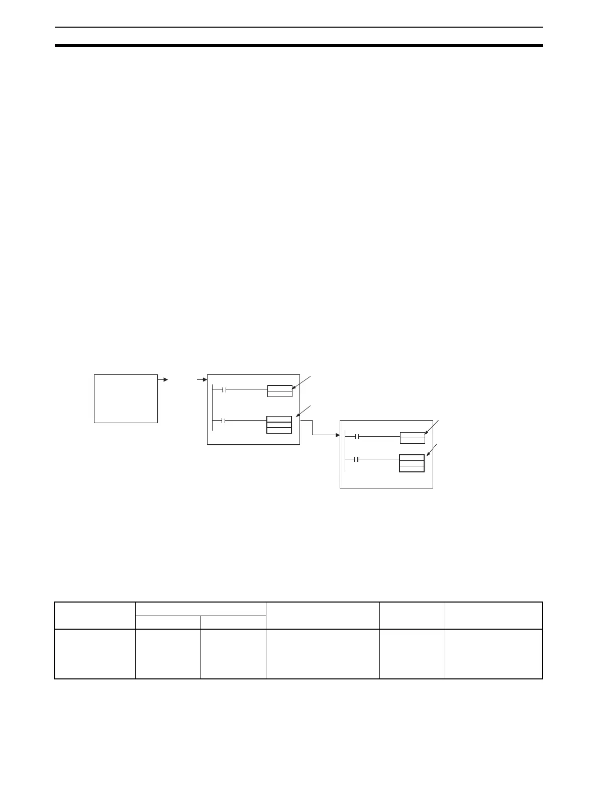
Example:
1,2,3... 1. Input interrupt task starts when the built-in input bit turns ON.
2. Output bit A turns ON in the input interrupt task, and the MSKS(690) in-
struction is executed to perform a scheduled interrupt reset start.
3. After a fixed interval, the scheduled interrupt task starts, and output bit A
in the scheduled interrupt task turns OFF, and the MSKS(690) instruction
is executed to prohibit a scheduled interrupt.
6-5-1 Setting the Scheduled Interrupt to Units of 0.1 ms
The scheduled interrupt time is set using the PLC Setup’s scheduled interrupt
unit time setting and the MSKS(690) instruction.
With CJ1M CPU Units, the scheduled interrupt time can be set in units of
0.1 ms between a minimum interval of 0.5 ms and the maximum interval of
999.9 ms.
PLC Setup
Input interrupt task
MSKS
14
#0005
Scheduled interrupt task
MSKS
4
#000 0
SET
A
A
Cyclic task
Input
interrupt
ON
Output bit A
turns ON.
Scheduled interrupt
reset start.
Fixed interval
Example:
After 0.5 ms)
Output bit A
turns OFF.
Stop due to fixed
interrupt being
prohibited.
RESET
Item PLC address Set value Default Refresh timing
Word Bit
Scheduled inter-
rupt unit time set-
ting
195 00 to 03 0 hex: 10-ms unit
1 hex: 1-ms unit
2 hex: 0.1-ms unit (CJ1M
CPU Units onlyÅj
0 hex When operation starts.