253
Index Registers Section 6-2
Instructions That Directly Address Index Registers
Index registers can be directly addressed by the following instructions.
DOUBLE SIGNED BINARY ADD WITHOUT CARRY: +L(401), DOUBLE
SIGNED BINARY SUBTRACT WITHOUT CARRY: –L(411), DOUBLE
INCREMENT BINARY: ++L(591), and DOUBLE DECREMENT BINARY: – –
L(593)
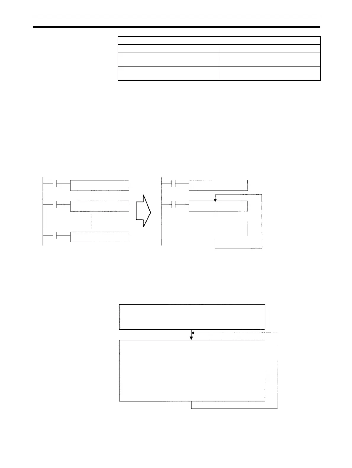
Example 1
The following example shows how an Index Register in a program loop can
replace a long series of instructions. In this case, instruction A is repeated n+1
times to perform some operation such as reading and comparing a table of
values.
Example 2
The following example uses Index Registers in a FOR–NEXT loop to define
and start 100 timers (T0000 to T099) with SVs contained in D00100 through
D00109. Each timer’s timer number and Completion Flag are specified in
Index Registers and the loop is repeated as the Index Registers are incre-
mented by one with each repetition.
Indirect addressing with DR offset DR@,IR@
Indirect addressing with auto-increment Increment by 1: ,IR@+
Increment by 2: ,IR@++
Indirect addressing with auto-decrement Decrement by 1: ,–IR@
Decrement by 2: ,– –IR@
Variation Syntax
Instruction A m
Instruction A m+1
Instruction A m+n
MOVR(560) m IR0
Add 1 to IR0 (n times)
Instruction A ,IR0+
Stores the PLC memory
address of m in IR0.
Repeats the process
in a loop such as
FOR-NEXT.
TIM starts the timer with the timer number (timer PV) indirectly
addressed by IR0+.
If the timer's Completion Flag (indirectly addressed by IR1+) is
ON, the work bit indirectly addressed by IR2+ is turned ON.
The IR0+, IR1+, and IR2+ variations increment the address in
the Index Register after referencing the address.
The ++ instruction increments D00000.
Repeated
MOVRW(561) stores the PLC memory address of T0000's PV in IR0.
MOVR(560) stores the PLC memory address of T0000's Completion Flag in
IR1.
MOVR(560) stores the PLC memory address of W00000 is stored in IR2.
 Loading...


