EasyManua.ls Logo

Omron SYSMAC CS/CJ Series User Manual

Omron SYSMAC CS/CJ Series
383 pages
To Next Page IconTo Next Page
To Previous Page IconTo Previous Page
Page #320 background imageLoading...
Page #320 background image
299
Diagnostic Functions Section 6-7
Logic Diagnosis Function
FPD(269) determines which input bit is causing the diagnostic output to
remain OFF and outputs that bit’s address. The output can be set to bit
address output (PLC memory address) or message output (ASCII).
If bit address output is selected, the PLC memory address of the bit can
be transferred to an Index Register and the Index Register can be indi-
rectly addressed in later processing.
If the message output is selected, the bit address will be registered in an
ASCII message that can be displayed on a Programming Device.
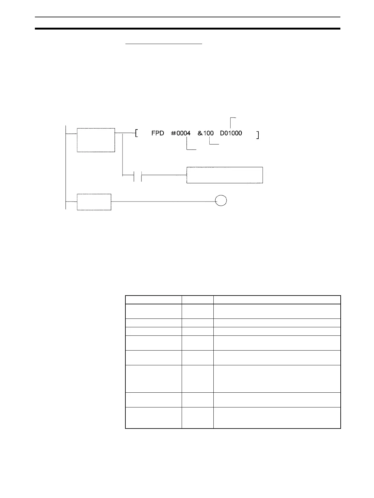
Time Monitoring:
Monitors whether output C goes ON with 10 seconds after input A. If C
doesn’t go ON within 10 seconds, a failure is detected and the Carry Flag
is turned ON. The Carry Flag executes the error-processing block. Also,
an FAL error (non-fatal error) with FAL number 004 is generated.
Logic Diagnosis:
FPD(269) determines which input bit in block B is preventing output C from
going ON. That bit address is output to D01000 and D01001.
Auxiliary Area Flags and Words
Error-processing block
Logic diagnosis
execution condition
B
C (Diagnostic output)
First register word
(Diagnostics output destination)
Monitoring time (0.1-s units):
10 s
Control data
(FAL 004, bit address output)
Carry Flag
FPD(269)
execution
condition
A
Name Address Operation
Error Code A400 When an error occurs, its error code is stored in
A400.
FAL Error Flag A40215 ON when FAL(006) is executed.
FALS Error Flag A40106 ON when FALS(007) is executed.
Executed FAL Num-
ber Flags
A360 to
A391
The corresponding flag is turned ON when an
FAL(006) or FALS(007) error occurs.
Error Log Area A100 to
A199
The Error Log Area contains information on the
most recent 20 errors.
Error Log Pointer A300 When an error occurs, the Error Log Pointer is
incremented by 1 to indicate where the next error
record will be recorded as an offset from the
beginning of the Error Log Area (A100).
Error Log Pointer
Reset Bit
A50014 Turn this bit ON to reset the Error Log Pointer
(A300) to 00.
FPD Teaching Bit A59800 Turn this bit ON when you want the monitoring
time to be set automatically when FPD(269) is
executed.

Table of Contents

Question and Answer IconNeed help?

Do you have a question about the Omron SYSMAC CS/CJ Series and is the answer not in the manual?

Omron SYSMAC CS/CJ Series Specifications

General IconGeneral
SeriesCS/CJ Series
CategoryController
Programming LanguagesLadder Diagram, Structured Text, Function Block Diagram, Sequential Function Chart
I/O CapacityVaries by model (e.g., up to 5120 I/O points)
Communication PortsRS-232C, RS-422/485
MountingDIN rail
Power SupplyAC or DC (varies by model)
CPU TypeVarious CPUs available within the CS/CJ series (e.g., CS1H, CS1G, CS1D, CJ1M, CJ2M, CJ2H)
Ethernet SupportYes (varies by model)
Operating Temperature0°C to 55°C (32°F to 131°F)

Summary

PRECAUTIONS

1 Intended Audience

Specifies the intended audience for this manual, requiring electrical system knowledge.

2 General Precautions

General guidelines for operating OMRON products according to specifications and consulting representatives.

3 Safety Precautions

Critical safety warnings regarding PLC usage, I/O memory, and handling units.

4 Operating Environment Precautions

Precautions for operating the PLC system in various environmental conditions.

5 Application Precautions

Precautions to observe when using the PLC system, including software and data transfer.

6 Conformance to EC Directives

Information on compliance with EMC and Low Voltage directives for CS/CJ PLCs.

SECTION 1: CPU Unit Operation

1-1 Initial Setup (CS1 CPU Units Only)

Procedures for initial setup and battery installation for CS1 CPU Units.

1-2 Using the Internal Clock (CS1 CPU Units Only)

How to set and use the internal clock for CS1 CPU Units.

1-3 Internal Structure of the CPU Unit

Overview of CPU Unit internal structure, memory, and diagrams.

1-4 Operating Modes

Description of PROGRAM, MONITOR, and RUN modes of the CPU Unit.

1-5 Programs and Tasks

Explains how programs are grouped into tasks for execution.

1-6 Description of Tasks

Details various types of tasks like cyclic and interrupt tasks.

SECTION 2: Programming

2-1 Basic Concepts

Fundamental concepts for writing CS/CJ-series PLC programs.

2-2 Precautions

Important precautions when programming, focusing on flags and sections.

2-3 Checking Programs

Procedures for checking programs for errors using CX-Programmer or console.

SECTION 3: Instruction Functions

3-1 Sequence Input Instructions

Instructions for handling input signals and execution conditions.

3-2 Sequence Output Instructions

Instructions for outputting results of logical processing to bits.

3-3 Sequence Control Instructions

Instructions for controlling program flow, such as END, JMP, and IL.

3-4 Timer and Counter Instructions

Details on various timer and counter instructions.

3-5 Comparison Instructions

Instructions for comparing values and creating execution conditions.

3-6 Data Movement Instructions

Instructions for transferring data between memory areas.

3-7 Data Shift Instructions

Instructions for shifting bits or words within data.

3-8 Increment/Decrement Instructions

Instructions for incrementing or decrementing numerical data.

3-9 Symbol Math Instructions

Instructions for performing arithmetic operations on signed binary and BCD data.

3-10 Conversion Instructions

Instructions for converting data between BCD, binary, and ASCII formats.

3-11 Logic Instructions

Instructions for performing logical operations (AND, OR, XOR) on bits and words.

3-12 Special Math Instructions

Instructions for specialized mathematical operations like square roots.

3-13 Floating-point Math Instructions

Instructions for performing mathematical operations on floating-point numbers.

3-14 Double-precision Floating-point Instructions (CS1-H, CJ1-H, or CJ1M Only)

Instructions for handling double-precision floating-point data.

3-15 Table Data Processing Instructions

Instructions for manipulating data in tables and stacks.

3-16 Data Control Instructions

Instructions for controlling data flow and scaling.

3-17 Subroutine Instructions

Instructions for calling and managing subroutines and macros.

3-18 Interrupt Control Instructions

Instructions for setting up and managing interrupt tasks.

3-19 High-speed Counter and Pulse Output Instructions (CJ1M-CPU22/23 Only)

Instructions for high-speed counter and pulse output.

3-20 Step Instructions

Instructions for step-by-step program execution.

3-21 Basic I/O Unit Instructions

Instructions for interacting with basic I/O units.

3-22 Serial Communications Instructions

Instructions for serial communications.

3-23 Network Instructions

Instructions for network communication.

3-24 File Memory Instructions

Instructions for manipulating file memory.

3-25 Display Instructions

Instructions for displaying messages.

3-26 Clock Instructions

Instructions for calendar and time operations.

3-27 Debugging Instructions

Instructions and functions for debugging programs.

3-28 Failure Diagnosis Instructions

Instructions for diagnosing and reporting failures.

3-29 Other Instructions

Miscellaneous instructions not covered elsewhere.

3-30 Block Programming Instructions

Instructions for creating and managing block programs.

3-31 Text String Processing Instructions

Instructions for processing text strings.

3-32 Task Control Instructions

Instructions for controlling task execution status.

SECTION 4: Tasks

4-1 Task Features

Overview of tasks, their advantages, and structure.

4-2 Using Tasks

How to use TASK ON/OFF instructions and manage task status.

4-3 Interrupt Tasks

Details on types, priority, flags, and precautions for interrupt tasks.

4-4 Programming Device Operations for Tasks

How to manage tasks using CX-Programmer and Programming Console.

SECTION 5: File Memory Functions

5-1 File Memory

Information on types of file memory, data, files, and procedures.

5-2 Manipulating Files

Procedures for reading, writing, and managing files using various methods.

5-3 Using File Memory

Procedures for initializing Memory Cards and EM File Memory.

SECTION 6: Advanced Functions

6-1 Cycle Time/High-speed Processing

Functions related to cycle time optimization and high-speed operations.

6-2 Index Registers

Explanation of index registers and their usage for indirect addressing.

6-3 Serial Communications

Details on serial communication protocols like Host Link and No-protocol.

6-4 Changing the Timer/Counter PV Refresh Mode

How to select and configure BCD or binary modes for timer/counter PVs.

6-5 Using a Scheduled Interrupt as a High-precision Timer (CJ1M Only)

Using scheduled interrupts as high-precision timers.

6-6 Startup Settings and Maintenance

Functions related to system startup, maintenance, and protection.

6-7 Diagnostic Functions

Overview of diagnostic tools like error logs and failure diagnosis.

6-8 CPU Processing Modes

Details on normal and parallel processing modes.

6-9 Peripheral Servicing Priority Mode

Settings for prioritizing peripheral servicing.

6-10 Battery-free Operation

Procedures for operating without a battery using flash memory or Memory Cards.

6-11 Other Functions

Includes I/O response time settings and I/O area allocation.

SECTION 7: Program Transfer, Trial Operation, and Debugging

7-1 Program Transfer

Procedures for transferring programs to the CPU Unit.

7-2 Trial Operation and Debugging

Functions for testing and debugging programs, including forced set/reset and tracing.

Appendix A: PLC Comparison Charts

Functional Comparison

Compares features like capacity, I/O points, and processing speed across PLC series.

PLC Comparison Charts

Detailed comparison of PLC features across different series.

Appendix B: Changes from Previous Host Link Systems

RS-232C Ports

Differences in wiring and other aspects for CS/CJ-series products.

RS-422A/485 Ports

Differences in wiring and other aspects for RS-422A/485 ports.

Related product manuals