105
DR 10 9989 (0089 + (10,000 – 0100))
CY 1 (negative result)
Second Subtraction
# 0000
DR 10 –9989
CY –0
DR 10 0011 (0000 + (10,000 – 9989))
CY 1 (negative result)
In the above case, the program would turn ON DR 1100 to indicate that the
value held in DR 10 is negative.
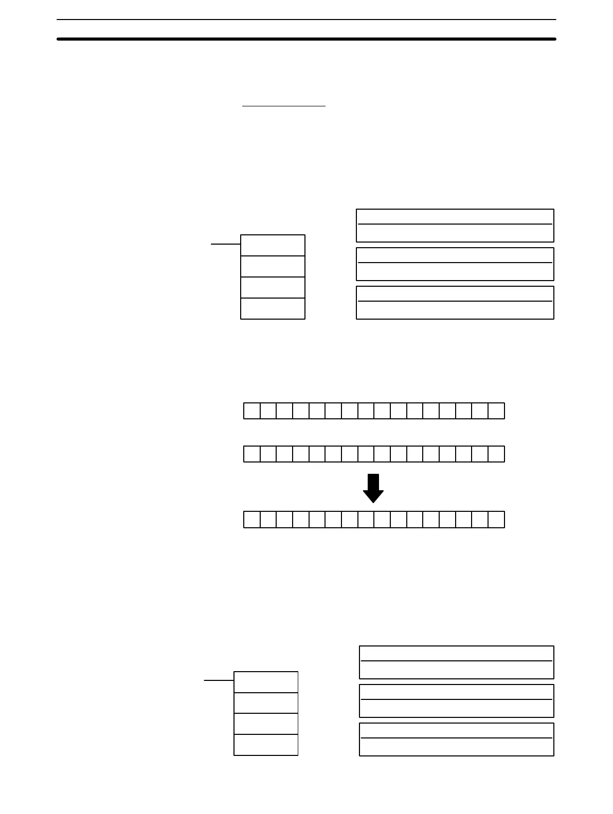
3-7-30 AND WORD- ANDW(42)
I1: Input 1
I/O, work, dedicated (03 only), DR, LR, TC, #
I2: Input 2
I/O, work, dedicated (03 only), DR, LR, TC, #
Ladder Symbol
Operand Data Areas
R: Result word
Output bits, work bits, DR, LR
ANDW(42)
I1
I2
R
When the execution condition is OFF, ANDW(42) is not executed. When the
execution condition is ON, ANDW(42) logically AND’s the contents of I1 and
I2 bit-by-bit and places the result in R.
10 0110 0110 011001
15 00
01 0101 0101 010101
00 0100 0100 010001
15 00
15 00
I1
I2
R
Example
ER: Indirectly addressed DR word is non-existent. (Content of *DR word
is not BCD, or the DR area boundary has been exceeded.)
EQ: ON when the result is 0.
3-7-31 OR WORD - ORW(43)
I1: Input 1
I/O, work, dedicated (03 only), DR, LR, TC, #
I2: Input 2
I/O, work, dedicated (03 only), DR, LR, TC, #
Ladder Symbol
Operand Data Areas
R: Result word
Output bits, work bits, DR, LR
ORW(43)
I1
I2
R
Description
Flags
Instruction Set Section 3-7