22
operation mode of the PC being monitored are identical, the following mes-
sage is displayed. The number in the top left corner indicates the number of
the PC being monitored, in this case PC #1.
1Ć000
B
When the mode switch of the Programming Console and the operation mode
of the PC being monitored are not identical, the following message is dis-
played.
<RUN>
MODE SET ERR
B
In this example, the message indicates that the Programming Console is set
to PRGM (program) mode, and that PC #1 is set to RUN mode. To clear the
error and reset the corresponding alarm, turn the Programming Console
mode to RUN and then change it back to PRGM mode. PC #1 will change to
PRGM mode.
Note If there is a communication error, the display will read “COMM ERR”.
2-4-2 Input Filters
To prevent the PC from malfunctioning due to the chattering (bouncing) of the
input device signals or induced noise, the input signals are received via a
filter. The filter may be adjusted so that input pulses of a duration less than a
minimum specified duration of the filter are ignored. The minimum duration
before the detection of an input signal may be set to 0, 1, 5, or 10 ms. The
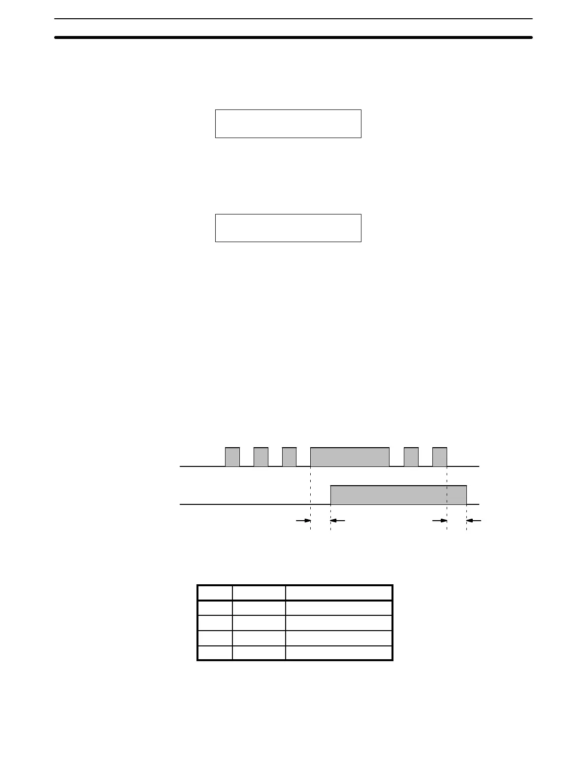
following diagram illustrates the use of a filter.
External input
Input detection time
tt
The input detection time, t, for the various possible settings is given in the
following table. The “key” column shows which key is pressed to input each
setting in the key sequence below.
Key Setting Actual detection time
0 0 ms t = 150 µs
1 1 ms t = 1 to 1.5 ms
2 5 ms t = 5 to 5.5 ms
3 10 ms t = 10 to 10.5 ms
During the period t to t + 0.5 ms, the positive and negative transitions of the
input signal may or may not be detected.
The filter values are set using the Programming Console. The input circuits
are grouped into three groups. The circuits included in each group depend on
Filter Value Settings
Programming Console Section 2-4
 Loading...