36
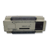
PC #0
PC #0
PC #1
PC #2
PC #3
DR 00
through
DR 07
PC #1
PC #0
PC #1
PC #2
PC #3
DR 00
through
DR 07
PC #2
PC #0
PC #1
PC #2
PC #3
DR 00
through
DR 07
PC #3
PC #0
PC #1
PC #2
PC #3
DR 00
through
DR 07
LR 00
LR 01
LR 02
LR 03
LR 04
LR 05
LR 06
LR 07
Write area Read area
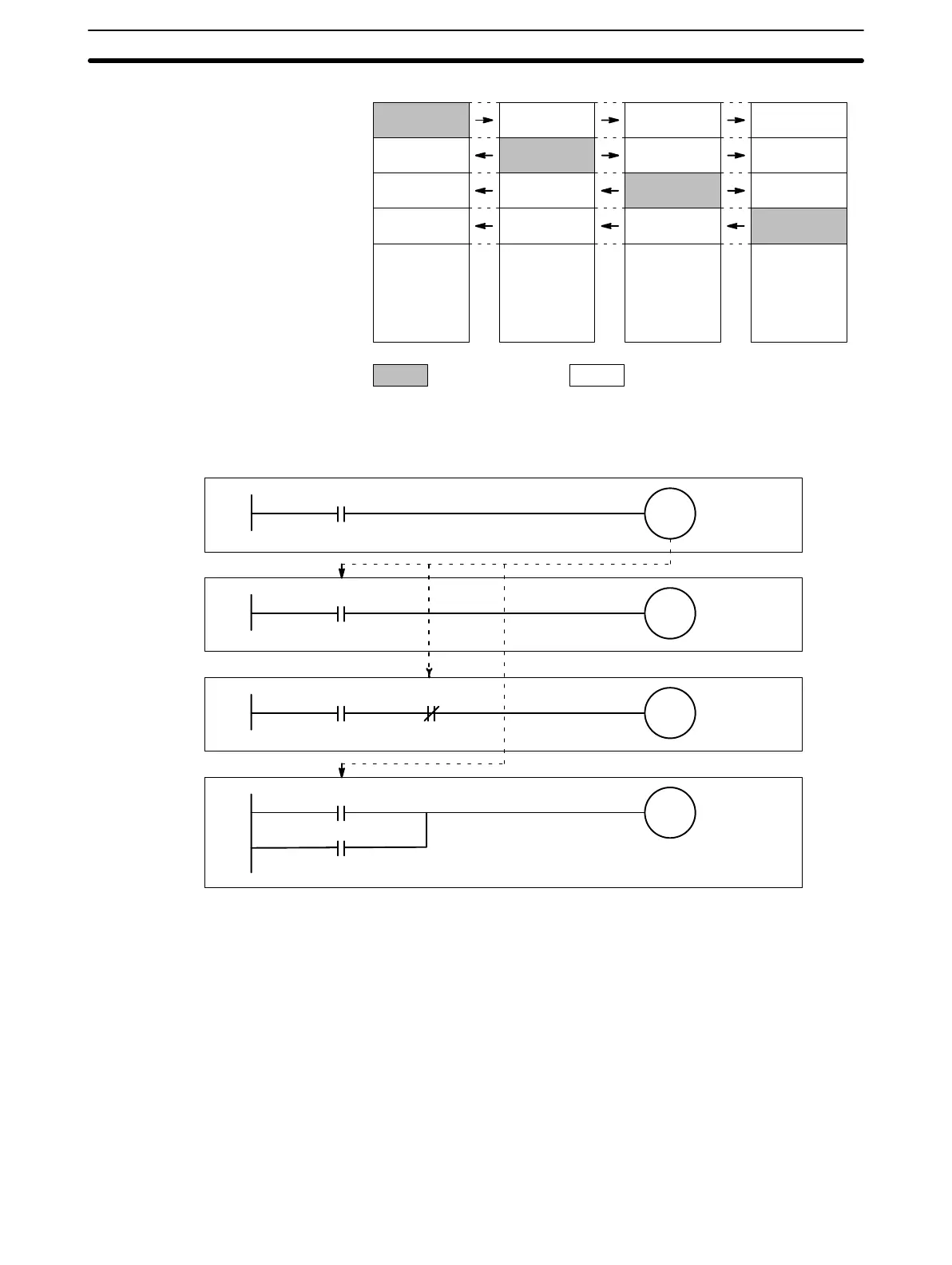
The following ladder diagrams illustrate an example of communications be-
tween linked PCs.
ON
LR 0000
LR 0000 ON
LR 0000
0100 ON
0200 OFF
LR 0000
0102 ON
PC #0
PC #1
PC #2
PC #3
When LR 0000 of PC #0 is turned ON, LR 0000 of PC #1, #2 and #3 are also
turned ON (OFF). LR 00 is the write area of PC #0, i.e., LR 00 of PC #1, #2
and #3 are used to read data written by PC #0.
3-2-6 DR Area
The DR area is used for data storage and manipulation. All data that is to be
preserved for power interruptions, must be placed in this area. The size of
the DR area depends on the size designated for the LR area (see 3-2-5 LR
Area for details).
3-2-7 TC (Timer/Counter) Area
The TC area is used to create and program timers and counters and holds
the Completion Flags, set values (SV), and present values (PV) for all timers
Data Link Communication
Example
Memory Areas Section 3-2
 Loading...